


Chapter 4 Signal Connections
National Instruments Corporation 4-43 AT-MIO/AI E Series User Manual
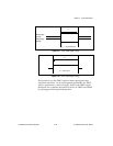
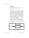
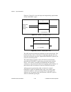
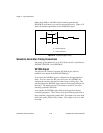
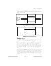
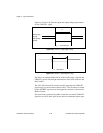
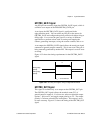
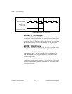
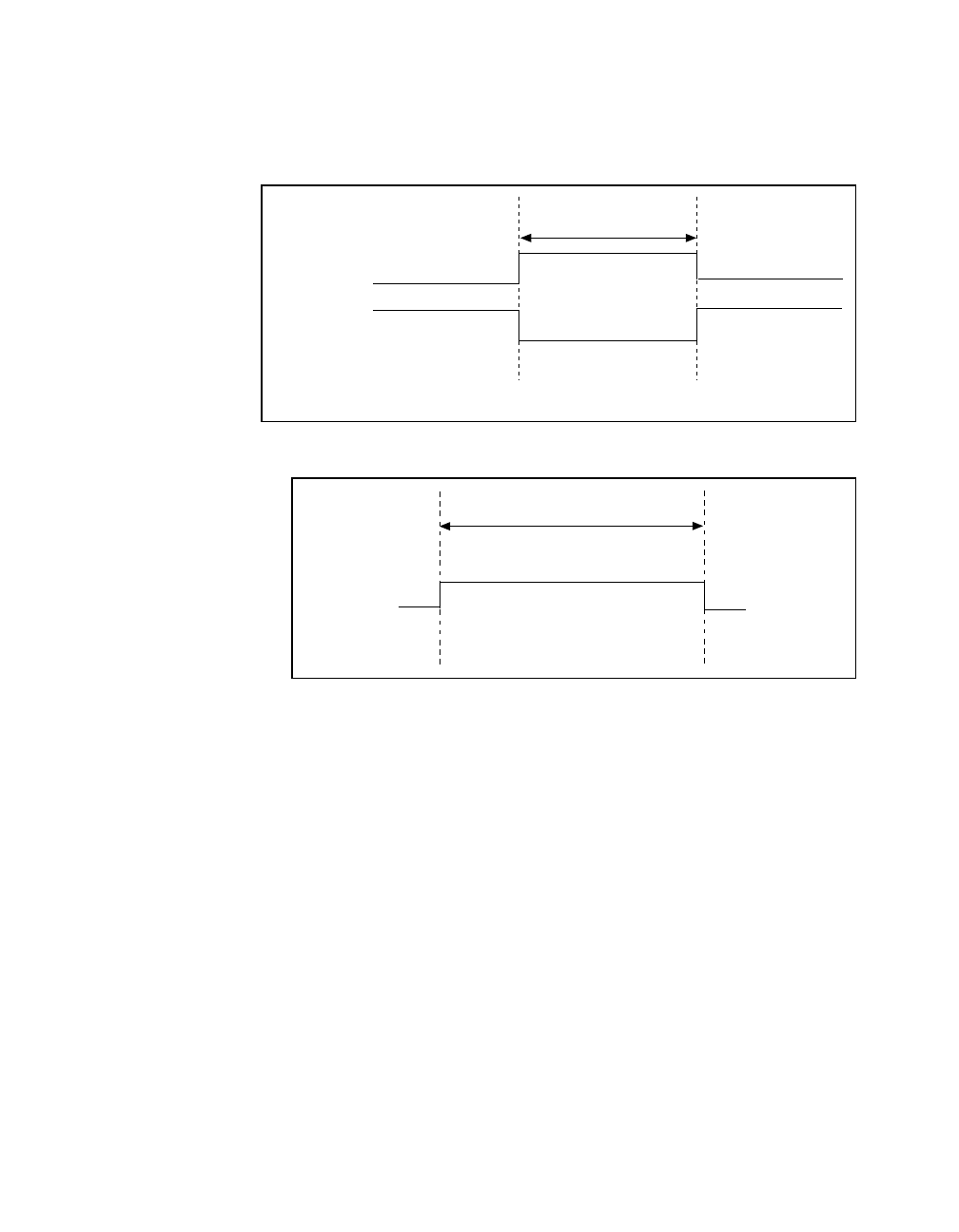
Figures 4-26 and 4-27 show the input and output timing requirements
for the WFTRIG signal.
Figure 4-26. WFTRIG Input Signal Timing
Figure 4-27. WFTRIG Output Signal Timing
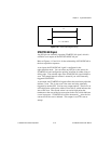
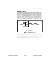
UPDATE* Signal
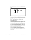
Any PFI pin can externally input the UPDATE* signal, which is
available as an output on the PFI5/UPDATE* pin.
As an input, the UPDATE* signal is configured in the edge-detection
mode. You can select any PFI pin as the source for UPDATE* and
configure the polarity selection for either rising or falling edge. The
selected edge of the UPDATE* signal updates the outputs of the DACs.
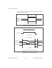
In order to use UPDATE*, you must set the DACs to posted-update
mode.
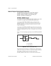
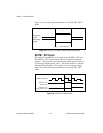
As an output, the UPDATE* signal reflects the actual update pulse that
is connected to the DACs. This is true even if the updates are being
externally generated by another PFI. The output is an active low pulse
with a pulse width of 300 to 350 ns. This output is set to tri-state at
startup.
Rising-edge
polarity
Falling-edge
polarity
t
w
t
w
= 10 ns minimum
t
w
t
w
= 50-100 ns