


Chapter 2 Installation and Configuration
National Instruments Corporation 2-3 AT-MIO/AI E Series User Manual
Plug and Play
The AT E Series boards are fully compatible with the industry-standard
Plug and Play ISA specification. A Plug and Play system arbitrates and
assigns resources through software, freeing you from manually setting
switches and jumpers. These resources include the board base I/O
address, DMA channels, and interrupt channels. Each AT E Series
board is configured at the factory to request these resources from the
Plug and Play Configuration Manager.
The Configuration Manager receives all of the resource requests at start
up, compares the available resources to those requested, and assigns the
available resources as efficiently as possible to the Plug and Play
boards. Application software can query the Configuration Manager to
determine the resources assigned to each board without your
involvement. The Plug and Play software is installed as a device driver
or as an integral component of the computer BIOS.
Switchless Data Acquisition
You can use an AT E Series board in a non-Plug and Play system as a
switchless DAQ board. A non-Plug and Play system is a system in
which the Configuration Manager has not been installed and which does
not contain any non-National Instruments Plug and Play products. You
use a configuration utility to enter the base address, DMA, and interrupt
selections, and the application software assigns them to the board.
Note: Avoid resource conflicts with non-National Instruments boards. For
example, do not configure two boards for the same base address.
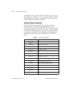
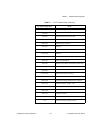
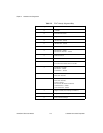
Base I/O Address Selection
The AT E Series boards can be configured to use base addresses in the
range of 20 to FFE0 hex. Each AT E Series board occupies 32 bytes of
address space and must be located on a 32-byte boundary. Therefore,
valid addresses include 100, 120, 140, ..., 3C0, 3E0 hex. This selection
is software configured and does not require you to manually change any
settings on the board.
DMA Channel Selection
The AT E Series boards can achieve high transfer rates by using up to
three 16-bit DMA channels. You can use these DMA channels for data
transfers with the analog input, analog output, and general-purpose
counter sections of the board. The AT E Series boards can use only