


Chapter 4 Signal Connections
National Instruments Corporation 4-7 AT-MIO/AI E Series User Manual
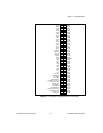
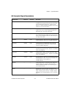
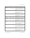
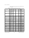
PFI2/CONVERT*
DGND Input
Output
PFI2/Convert—As an input, this is one of the PFIs.
As an output, this is the CONVERT* signal. A high-to-low
edge on CONVERT* indicates that an A/D conversion is
occurring.
PFI3/GPCTR1_SOURCE DGND Input
Output
PFI3/Counter 1 Source—As an input, this is one of the
PFIs.
As an output, this is the GPCTR1_SOURCE signal. This
signal reflects the actual source connected to the
general-purpose counter 1.
PFI4/GPCTR1_GATE DGND Input
Output
PFI4/Counter 1 Gate—As an input, this is one of the PFIs.
As an output, this is the GPCTR1_GATE signal. This signal
reflects the actual gate signal connected to the
general-purpose counter 1.
GPCTR1_OUT DGND Output Counter 1 Output—This output is from the general-purpose
counter 1 output.
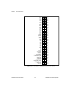
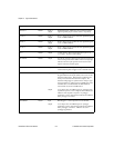
PFI5/UPDATE* DGND Input
Output
PFI5/Update—As an input, this is one of the PFIs.
As an output, this is the UPDATE* signal. A high-to-low
edge on UPDATE* indicates that the analog output primary
group is being updated.
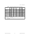
PFI6/WFTRIG DGND Input
Output
PFI6/Waveform Trigger—As an input, this is one of the
PFIs.
As an output, this is the WFTRIG signal. In timed analog
output sequences, a low-to-high transition indicates the
initiation of the waveform generation.
PFI7/STARTSCAN DGND Input
Output
PFI7/Start of Scan—As an input, this is one of the PFIs.
As an output, this is the STARTSCAN signal. This pin
pulses once at the start of each analog input scan in the
interval scan. A low-to-high transition indicates the start of
the scan.
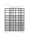
PFI8/GPCTR0_SOURCE DGND Input
Output
PFI8/Counter 0 Source—As an input, this is one of the
PFIs.
As an output, this is the GPCTR0_SOURCE signal. This
signal reflects the actual source connected to the
general-purpose counter 0.
Signal Name
Reference Direction Description
(Continued)