


Chapter 3 Hardware Overview
AT-MIO/AI E Series User Manual 3-8
National Instruments Corporation
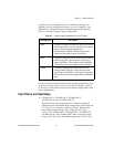
You can program polarity and range settings on a per channel basis
so that you can configure each input channel uniquely.
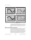
The software-programmable gain on these boards increases their
overall flexibility by matching the input signal ranges to those that
the ADC can accommodate. The AT-MIO-16E-1, AT-MIO-16E-2,
AT-MIO-64E-3, AT-MIO-16E-10, and AT-MIO-16DE-10 have
gains of 0.5, 1, 2, 5, 10, 20, 50, and 100 and are suited for a wide
variety of signal levels. With the proper gain setting, you can use
the full resolution of the ADC to measure the input signal.
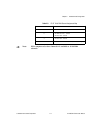
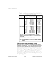
Table 3-2 shows the overall input range and precision according to
the input range configuration and gain used.
Table 3-2. Actual Range and Measurement Precision
Range
Configuration
Gain Actual Input Range Precision
1
0 to +10 V
1.0
2.0
5.0
10.0
20.0
50.0
100.0
0 to +10 V
0 to +5 V
0 to +2 V
0 to +1 V
0 to +500 mV
0 to +200 mV
0 to +100 mV
2.44 mV
1.22 mV
488.28 µV
244.14 µV
122.07 µV
48.83 µV
24.41 µV
-5 to +5 V 0.5
1.0
2.0
5.0
10.0
20.0
50.0
100.0
-10 to +10 V
-5 to +5 V
-2.5 to +2.5 V
-1 to +1 V
-500 to +500 mV
-250 to +250 mV
-100 to +100 mV
-50 to +50 mV
4.88 mV
2.44 mV
1.22 mV
488.28 µV
244.14 µV
122.07 µV
48.83 µV
24.41 µV
1
The value of 1 LSB of the 12-bit ADC; that is, the voltage
increment corresponding to a change of one count in the ADC
12-bit count.
Note: See Appendix A, Specifications, for absolute maximum
ratings.