


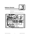

Chapter 3 Hardware Overview
National Instruments Corporation 3-7 AT-MIO/AI E Series User Manual
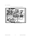
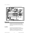
programmed on a per channel basis for multimode scanning. For
example, you can configure the circuitry to scan 12 channels—four
differentially configured channels and eight single-ended channels.
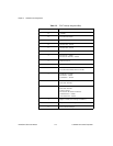
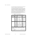
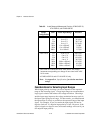
Table 3-1 describes the three input configurations.
For more information about the three types of input configuration, refer
to the Analog Input Signal Connections section in Chapter 4, Signal
Connections, which contains diagrams showing the signal paths for the
three configurations.
Input Polarity and Input Range
♦ AT-MIO-16E-1, AT-MIO-16E-2, AT-MIO-64E-3,
AT-MIO-16E-10, and AT-MIO-16DE-10
These boards have two input polarities—unipolar and bipolar.
Unipolar input means that the input voltage range is between 0 and
V
ref
, where V
ref
is a positive reference voltage. Bipolar input
means that the input voltage range is between -V
ref
/2
and
+V
ref
/2. The AT-MIO-16E-1, AT-MIO-16E-2, AT-MIO-64E-3,
AT-MIO-16E-10, and AT-MIO-16DE-10
have a unipolar input
range of 10 V (0 to 10 V) and a bipolar input range of 10 V (±5 V).
Table 3-1. Available Input Configurations for the AT E Series
Configuration
Description
DIFF
A channel configured in DIFF mode uses two analog
channel input lines. One line connects to the positive
input of the board programmable gain
instrumentation amplifier (PGIA), and the other
connects to the negative input of the PGIA.
RSE A channel configured in RSE mode uses one analog
channel input line, which connects to the positive
input of the PGIA. The negative input of the PGIA
is internally tied to analog input ground (AIGND).
NRSE A channel configured in NRSE mode uses one
analog channel input line, which connects to the
positive input of the PGIA. The negative input of the
PGIA connects to the analog input sense (AISENSE)
input.