


Chapter 4 Signal Connections
National Instruments Corporation 4-5 AT-MIO/AI E Series User Manual
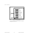
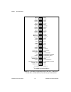
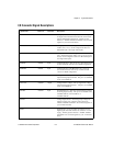
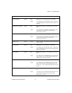
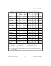
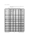
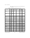
I/O Connector Signal Descriptions
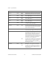
Signal Name
Reference Direction Description
AIGND
— — Analog Input Ground—These pins are the reference point
for single-ended measurements and the bias current return
point for differential measurements. All three ground
references—AIGND, AOGND, and DGND—are connected
together on your AT E Series board.
ACH<0..15> AIGND Input Analog Input Channels 0 through 15—Each channel pair,
ACH<i, i+8> (i = 0..7), can be configured as either one
differential input or two single-ended inputs.
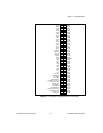
ACH<16..63> AIGND Input Analog Input Channels 16 through 63 (AT-MIO-64E-3
only)—Each channel pair, ACH<i, i+8> (i = 16..23, 32..39,
48..55), can be configured as either one differential input or
two single-ended inputs.
AISENSE AIGND Input Analog Input Sense—This pin serves as the reference node
for any of channels ACH <0..15> in NRSE configuration.
AISENSE2 AIGND Input Analog Input Sense (AT-MIO-64E-3 only)—This pin
serves as the reference node for any of channels ACH
<16..63> in NRSE configuration.
DAC0OUT AOGND Output Analog Channel 0 Output—This pin supplies the voltage
output of analog output channel 0. This pin is not available
on the AT-AI-16XE-10.
DAC1OUT AOGND Output Analog Channel 1 Output—This pin supplies the voltage
output of analog output channel 1. This pin is not available
on the AT-AI-16XE-10.
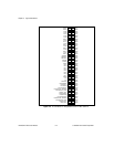
EXTREF AOGND Input External Reference—This is the external reference input for
the analog output circuitry. This pin is not available on the
AT-MIO-16XE-10, AT-AI-16XE-10, or
AT-MIO-16XE-50.
AOGND — — Analog Output Ground—The analog output voltages are
referenced to this node. All three ground references—
AIGND, AOGND, and DGND—are connected together on
your AT E Series board.
DGND — — Digital Ground—This pin supplies the reference for the
digital signals at the I/O connector as well as the +5 VDC
supply. All three ground references—AIGND, AOGND,
and DGND—are connected together on your AT E Series
board.