


Chapter 4 Signal Connections
AT-MIO/AI E Series User Manual 4-8
National Instruments Corporation
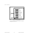
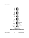
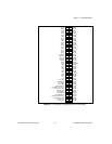
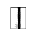
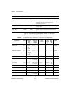
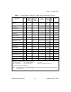
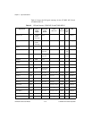
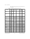
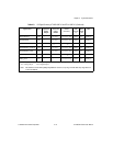
Table 4-1 shows the I/O signal summary for the AT-MIO-16E-1,
AT-MIO-16E-2 and AT-MIO-64E-3.
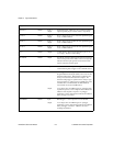
PFI9/GPCTR0_GATE
DGND Input
Output
PFI9/Counter 0 Gate—As an input, this is one of the PFIs.
As an output, this is the GPCTR0_GATE signal. This signal
reflects the actual gate signal connected to the
general-purpose counter 0.
GPCTR0_OUT DGND Output Counter 0 Output—This output is from the general-purpose
counter 0 output.
FREQ_OUT DGND Output Frequency Output—This output is from the frequency
generator output.
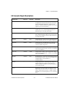
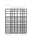
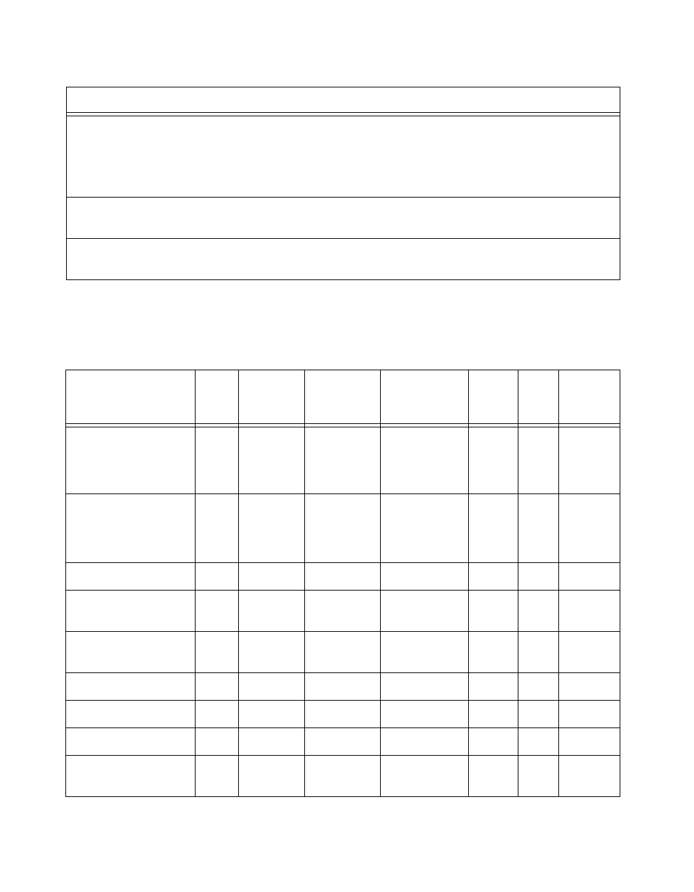
Table 4-1. I/O Signal Summary, AT-MIO-16E-1, AT-MIO-16E-2, and AT-MIO-64E-3
Signal Name
Drive Impedance
Input/
Output
Protection
(Volts)
On/Off
Source
(mA at V)
Sink
(mA at
V)
Rise
Time
(ns)
Bias
ACH<0..63>
AI 100 GΩ
in parallel
with
100 pF
25/15 — — —
±200 pA
AISENSE, AISENSE2 AI 100 GΩ
in parallel
with
100 pF
25/15 — — —
±200 pA
AIGND AO — — — — — —
DAC0OUT AO 0.1 Ω
Short-circuit
to ground
5 at 10 5 at -10 20
V/µs
—
DAC1OUT AO 0.1 Ω
Short-circuit
to ground
5 at 10 5 at -10 20
V/µs
—
EXTREF AI 10 kΩ
25/15
— — — —
AOGND AO — — — — — —
DGND DO — — — — — —
VCC DO 0.1Ω
Short-circuit
to ground
1A — — —
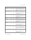
Signal Name
Reference Direction Description
(Continued)