


Chapter 4 Signal Connections
National Instruments Corporation 4-29 AT-MIO/AI E Series User Manual
Warning: Exceeding the maximum input voltage ratings, which are listed in
Tables 4-1 through 4-4, can damage the AT E Series board and the PC.
National Instruments is
NOT
liable for any damages resulting from such
signal connections.
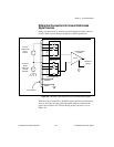
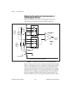
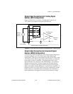
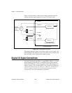
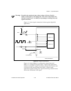
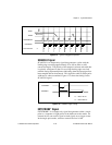
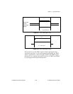
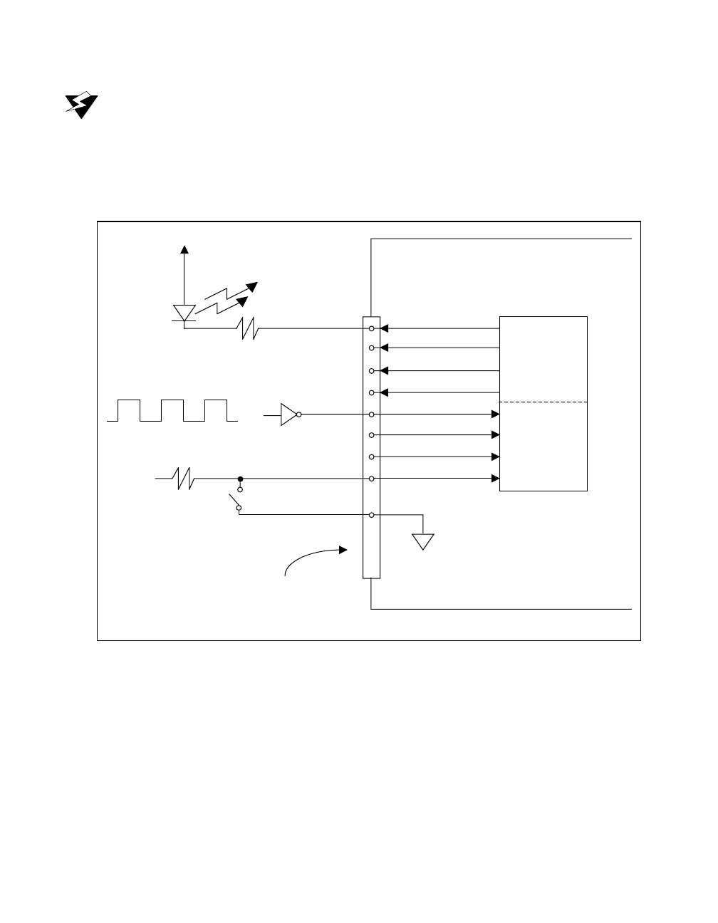
Figure 4-11 shows signal connections for three typical digital I/O
applications.
Figure 4-11. Digital I/O Connections
Figure 4-11 shows DIO<0..3> configured for digital input and
DIO<4..7> configured for digital output. Digital input applications
include receiving TTL signals and sensing external device states such
as the state of the switch shown in the figure. Digital output
applications include sending TTL signals and driving external devices
such as the LED shown in the figure.
LED
+5 V
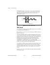
TTL Signal
+5 V
DIO<4..7>
DIO<0..3>
DGND
Switch
I/O Connector
AT E Series Board