


Network and System Management
327
ProSafe Wireless-N 8-Port Gigabit VPN Firewall FVS318N
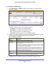
To configure the SNMP settings:
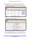
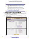
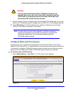
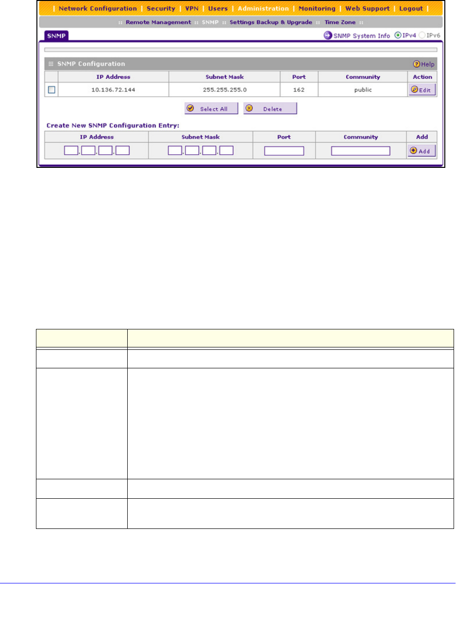
1. Select Administration > SNMP. The SNMP screen displays. (The following figure
contains an example.)
Figure 196.
The SNMP Configuration table shows the following columns:
• IP
Address. The IP address of the SNMP manager.
• Sub
net Mask. The subnet mask of the SNMP manager.
• Port. T
he trap port number of the SNMP manager.
• Com
munity. The trap community string of the SNMP manager.
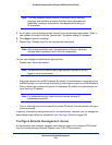
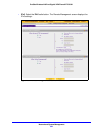
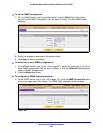
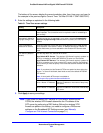
2. T
o specify a new SNMP configuration, in the Create New SNMP Configuration Entry section
of the screen, enter the settings as explained in the following table:
3. Click Add
to add the new SNMP configuration to the SNMP Configuration table.
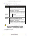
Table 79. SNMP screen settings
Setting Description
IP Address Enter the IP address of the new SNMP manager.
Subnet Mask Enter the subnet mask of the
new SNMP manager.
Note the following:
• If you want to narrow down the number of device
s that can access the wireless
VPN firewall through the host IP address and receive traps, enter an IP address
with a subnet mask of 255.255.255.252.
• If you want to allow a subnet to access the wireless VPN firewall through the host
IP a
ddress and receive traps, enter an IP address with a subnet mask of
255.0.0.0. The traps are received at the IP address, but almost the entire subnet
has access through the community string.
Port Enter the port number of the new SNMP man
ager. The default port number is 162.
Community Enter the community string that allows the SNMP manager access to the MIB
o
bjects of the wireless VPN firewall for the purpose of reading only.