


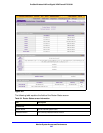

Monitor System Access and Performance
343
ProSafe Wireless-N 8-Port Gigabit VPN Firewall FVS318N
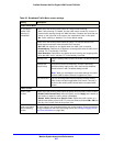
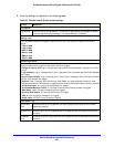
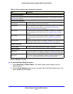
This section describes steps 2 through 4, using the topology that is described in the following
table:
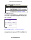
Configure Gateway 1 at Site 1
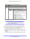
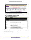
To create a gateway-to-gateway VPN tunnel to Gateway 2, using the IPSec VPN wizard:
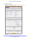
1. Select VPN > IPSec VPN
> VPN Wizard. The VPN Wizard screen displays.
2. Conf
igure a gateway-to-gateway VPN tunnel using the following information:
• Con
nection name. Any name of your choice
• Pre
-shared key. Any key of your choice
• Remote W
AN IP address. 10.0.0.2
• L
ocal WAN IP address. 10.0.0.1
• Remote L
AN IP Address. 192.168.20.0
• Remote L
AN subnet mask. 255.255.255.0
3. Click App
ly to save the settings.
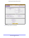
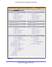
To change the remote IP address in the VPN policy:
1. Select VPN > IPSec VPN
> VPN Policies. The VPN Policy screen displays.
2. Next to th
e policy name for the Gateway 1–to–Gateway 2 autopolicy, click Edit. The Edit
VPN Policy screen displays.
3. In the Genera
l section of the screen, clear the Enable NetBIOS check box.
4. In the T
raffic Selector section of the screen, make the following changes:
• F
rom the Remote IP drop-down list, select Single.
• I
n the Start IP fields, type 10.0.0.2, which is the WAN IP address of Gateway 2.
5. Click App
ly to save the settings.
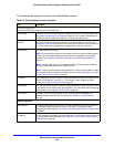
Configure Gateway 2 at Site 2
To create a gateway-to-gateway VPN tunnel to Gateway 1, using the IPSec VPN wizard:
1. Select VPN > IPSec VPN
> VPN Wizard. The VPN Wizard screen displays.
2. Conf
igure a gateway-to-gateway VPN tunnel using the following information:
• Con
nection name. Any name of your choice
• Pre
-shared key. The same key as you configured on Gateway 1
Type of Address Gateway 1 at Site 1 Gateway 2 at Site 2
WAN IP address 10.0.0.1 10.0.0.2
LAN IP address 192.168.10.0 192.168.20.0
LAN subnet mask 255.255.255.0 255.255.255.0
LAN IP address syslog server 192.168.10.2 Not applicable