


Using the Console Interface
302401-D Rev 00
3-5
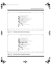
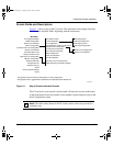
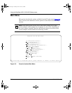
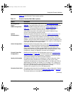
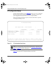
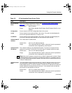
Table 3-1 describes the CI main menu options.
Table 3-1. Console Interface Main Menu options
Option Description
IP Configuration/
Setup...
Displays the IP Configuration/Setup screen (see “
IP Configuration/Setup” on
page 3-8
). This screen allows you to set or modify IP configuration parameters.
SNMP Configuration...
Displays the SNMP Configuration screen (see “
SNMP Configuration” on
page 3-13
). This screen allows you to set or modify the SNMP read-only
community and read-write community strings, enable or disable the
authentication trap and the link Up/down trap, set the IP address of trap
receivers, and set the trap community strings.
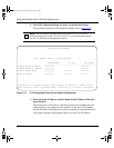
System
Characteristics...
Displays the System Characteristics screen (see “
System Characteristics” on
page 3-15
). This screen allows you to view switch characteristics, including
number of resets, power status, hardware and firmware version, and MAC
address. This screen also contains three user-configurable fields: sysContact,
sysName, and sysLocation. When the switch is part of a stack configuration, this
screen also displays the base unit identification, the number of units configured
in the stack, and the local unit stack number.
Switch Configuration...
Displays the Switch Configuration Menu screen (see “
Switch Configuration” on
page 3-18
). This menu provides the following configuration options: MAC
Address Table, VLAN Configuration, Port Configuration, High speed Flow
Control Configuration (only when a gigabit MDA is installed), MultiLink Trunk
Configuration, Port Mirroring Configuration, Rate Limiting Configuration, IGMP
Configuration, Display Port Statistics, and Clear All Port Statistics.
Console/Comm Port
Configuration...
Displays the Console/Comm Port Configuration screen (see “
Console/Comm
Port Configuration” on page 3-58). This screen allows you to configure and
modify the console/Comm port parameters, including the console port speed
and password settings for the switch and stack operation.
Identify Unit Numbers
Only appears when the switch is participating in a stack configuration. When
selected, this option identifies the unit numbering of each unit in a stack
configuration by lighting the corresponding number of (100 Mb/s) port LEDs for
approximately 10 seconds. For example, in a 4-unit stack, unit 1 displays one
LED, unit 2 displays two LEDs, unit 3 displays three LEDs, and unit 4 displays
four LEDs. The LED displays
temporarily
override any existing
100 Mb/s LED indications on all unit LED display panels.
Renumber Stack Units
Only appears when the switch is participating in a stack configuration. Displays
the Renumber Stack Units screen (see “
Renumber Stack Units” on page 3-65).
This screen allows you to renumber the units at any time.
(continued)
kombk.book Page 5 Tuesday, June 29, 1999 3:25 PM