Using the BayStack 450 10/100/1000 Series Switch
3-34
302401-D Rev 00
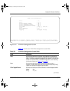
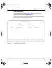
High Speed Flow Control Configuration
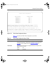
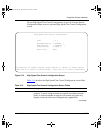
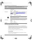
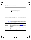
The High Speed Flow Control Configuration screen (Figure 3-15) allows you to
set the port parameters for installed gigabit MDAs.
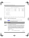
Port
Indicates the switch port numbers that correspond to the field values in that row of
the screen (for example, the field values in row 2 apply to switch port 2). The values
that you set in the
Switch
row will affect all switch ports and, when the switch is part
of a stack, the values that you set in the
Stack
row will affect all ports in the entire
stack (except the gigabit MDA ports or fiber optic ports, when installed).
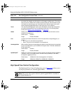
Trunk
The read-only data displayed in this column indicates the trunks that correspond to
the switch ports specified in the Trunk Members fields of the Trunk Configuration
screen (see “MultiLink Trunk Configuration” on page 3-37).
Status
Allows you to disable any of the switch ports. You can also use this field to control
access to any switch port.
Default Value Enabled
Range Enabled, Disabled
Link
A read-only field that indicates the current link state of the corresponding port, as
follows:
• Up: The port is connected and operational.
• Down: The port is not connected or is not operational.
Autonegotiation
When enabled, sets the corresponding port speed to match the best service provided
by the connected station, up to 100 Mb/s in full-duplex mode. This field is disabled for
all fiber optic ports.
Default Value Enabled
Range Enabled, Disabled
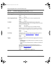
Speed/Duplex
1
Allows you to manually configure any port to support an Ethernet speed of 10 Mb/s or
100 Mb/s, in half- or full-duplex mode. This field is set (by default) to 1000 Mb/s,
full-duplex for gigabit ports only.
Default Value 100Mbs/Half (when Autonegotiation is Disabled)
Range 10Mbs/Half, 10Mbs/Full, 100Mbs/Half, 100Mbs/Full
1 Fiber optic ports can only be set to 100 Mb/s/Half or 100 Mb/s Full.
Note:
This screen only appears when an optional gigabit MDA is installed in
the Uplink Module slot.
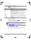
Table 3-12. Port Configuration Screen Fields
(continued)
Field Description
kombk.book Page 34 Tuesday, June 29, 1999 3:25 PM


