


Using the BayStack 450 10/100/1000 Series Switch
1-28
302401-D Rev 00
Stack Up Configurations
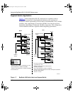
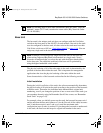
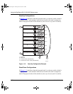
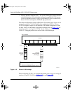
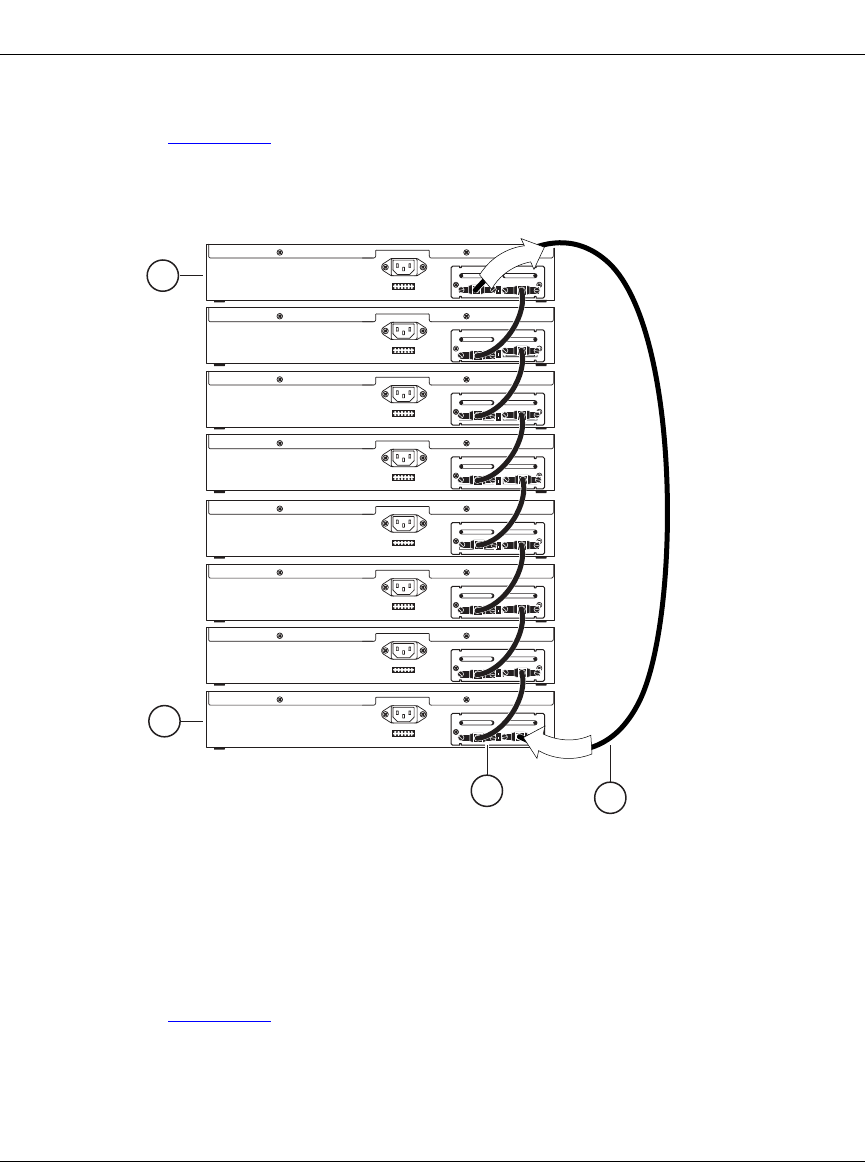
In Figure 1-12
, data flows from the base unit (unit 1) to the next switch, which is
assigned as unit 2, and continues until the last switch in the stack is assigned as
unit 8. The physical order of the switches is from bottom to top (unit 1 to unit 8).
Figure 1-12. Stack Up Configuration Example
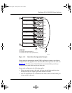
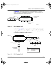
Stack Down Configurations
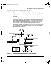
In Figure 1-13
, data flows from the base unit (unit 1) to the next switch, which is
assigned as unit 2, and continues until the last switch in the stack is assigned as
unit 8. The physical order of the switches is from top to bottom (unit 1 to unit 8).
Unit 7
Unit 8
1 = Last unit
2 = Base unit
3 = Cascade cable (PN 303978-A)
4 = Cascade max-return cable (PN 303979-A)
BS0033B
Unit 5
Unit 6
Unit 3
Unit 4
Unit 1
Unit 2
2
1
3
O
u
t
I
n
4
kombk.book Page 28 Tuesday, June 29, 1999 3:25 PM