


Using the BayStack 450 10/100/1000 Series Switch
1-2
302401-D Rev 00
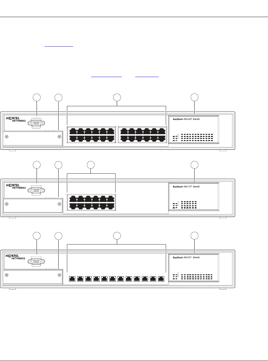
Front Panel
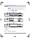
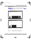
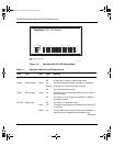
Figure 1-2 shows the front-panel configurations for the three BayStack 450 switch
models. Descriptions of the front-panel components follow the figures.
For a description of the components located on the back panel of the BayStack
450 switch, see “Back Panel
” on page 1-8.
Figure 1-2. BayStack 450 Switch Front Panels
1
2
3
4
= Comm Port
= Uplink/Expansion slot
= Port connectors
= LED display panel
BS45002B
Uplink/Expansion Module
2826 2725
Comm Port
17 1913 15 21
18 2014 16 22 24
23
Status
Dwn
Pwr Up
Cas
RPSU Base
Activity
Activity
10/100
10/100
1
2
3
4
BayStack 450-24T
5713 9
682 4 10 12
11
Uplink/Expansion Module
16
Comm Port
13 1514
RPSU
Dwn
Pwr
Cas
Up
Status
Base
Activity
Activity
10/100
10/100
1
2
3 4
BayStack 450-12T
5713 9
682 4 10 12
11
Uplink/Expansion Module
1614 1513
Comm Port
Status
Dwn
Pwr Up
Cas
RPSU Base
Activity
Link
F Dx
1
2
3
4
BayStack 450-12F
5713 96824 10 1211
kombk.book Page 2 Tuesday, June 29, 1999 3:25 PM