


160
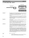
If the execution condition remains ON long enough for TIM to time down to zero,
the Completion Flag for the TC number used will turn ON and will remain ON
until TIM is reset (i.e., until its execution condition is goes OFF).
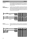
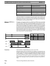
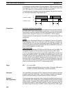
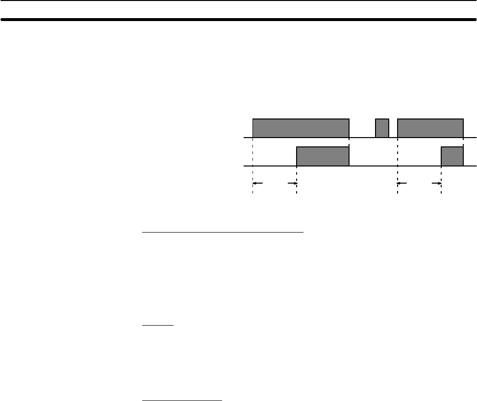
The following figure illustrates the relationship between the execution condition
for TIM and the Completion Flag assigned to it.
Execution condition
Completion Flag
ON
OFF
ON
OFF
SV SV
Precautions Interlocks and Power Interruptions
Timers in interlocked program sections are reset when the execution condition
for IL(02) is OFF. Power interruptions also reset timers. If a timer that is not reset
under these conditions is desired, SR area clock pulse bits can be counted to
produce timers using CNT. Refer to 5-14-4 COUNTER – CNT for details.
Program execution will continue even if a non-BCD SV is used, but timing will not
be accurate.
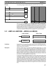
Jumps
Never program TIM between JMP(04) 00 and JME(05) 00 with an SV of #0000.
The Completion Flag will turn ON even when the execution condition for
JMP(04) 00 is ON (i.e., even when the program section with TIM is jumped). TIM
can be programmed successfully between JMP(04) and JME(05) as long as a
jump number between 01 and 99 is used.
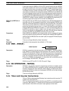
Step Instructions
Never program TIM between STEP(08) and SNXT(09) with an SV of #0000. The
Completion Flag will turn ON even when the step containing TIM is reset.
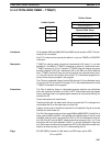
The SV of the timers can be set in the range #0000 to #9999 (BCD). If the SV for a
timer is set to #0000 or #0001, it will operate in the following way. If the SV is set
to #0000, when the timer input goes from OFF to ON, the Completion Flag will
turn ON. If the SV is set to #0001, because the timer accuracy is 0 to –0.1 s, the
actual time will be a value between 0 and 0.1 s, and the Completion Flag may
turn ON as soon as the timer input goes from OFF to ON. With other values also,
allow for a timer accuracy of 0 to –0.1 s when setting the SV.
Flags ER: SV is not in BCD.
Indirectly addressed DM word is non-existent. (Content of DM word is
not BCD, or the DM area boundary has been exceeded.)
Examples All of the following examples use OUT in diagrams that would generally be used
to control output bits in the IR area. There is no reason, however, why these dia-
grams cannot be modified to control execution of other instructions.
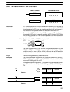
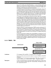
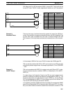
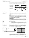
The following example shows two timers, one set with a constant and one set via
input word 005. Here, 00200 will be turned ON after 00000 goes ON and stays
ON for at least 15 seconds. When 00000 goes OFF, the timer will be reset and
00200 will be turned OFF. When 00001 goes ON, TIM 001 is started from the SV
provided through IR word 005. Bit 00201 is also turned ON when 00001 goes
Example 1:
Basic Application
Timer and Counter Instructions Section 5-14