173
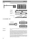
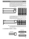
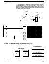
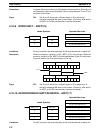
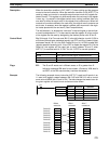
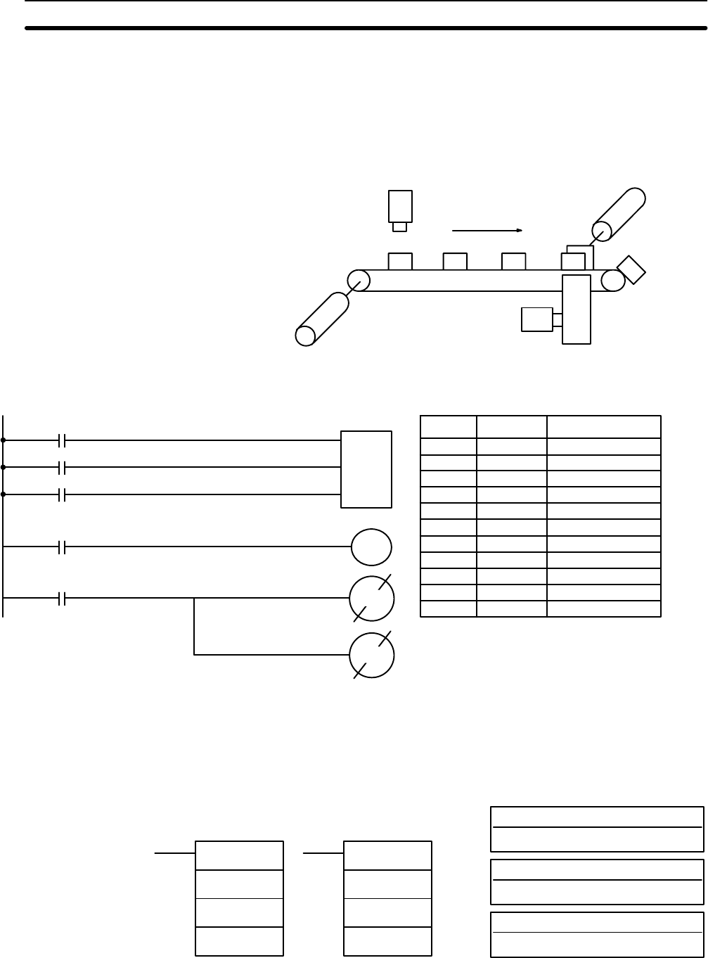
The program is set up so that a rotary encoder (00000) controls execution of
SFT(10) through a DIFU(13), the rotary encoder is set up to turn ON and OFF
each time a product passes the first sensor. Another sensor (00002) is used to
detect faulty products in the shoot so that the pusher output and HR 0003 of the
shift register can be reset as required.
Chute
(00500)
Sensor
(00001)
Rotary Encoder
(00000)
Pusher
Sensor
(00002)
I
P
SFT(10)
HR 00
HR 01
R
00001
00000
00003
00500
HR 0003
00500
HR 0003
00002
Address Instruction Operands
00000 LD 00001
00001 LD 00000
00002 LD 00003
00003 SFT(10)
HR 00
HR 01
00004 LD HR 0003
00005 OUT 00500
00006 LD 00002
00007 OUT NOT 00500
00008 OUT NOT HR 0003
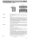
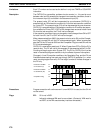
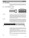
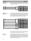
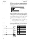
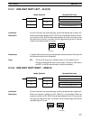
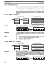
5-15-2 REVERSIBLE SHIFT REGISTER – SFTR(84)
C: Control word
IR, AR, DM, HR, LR
St: Starting word
IR, SR, AR, DM, HR, LR
Ladder Symbols
Operand Data Areas
E: End word
IR, SR, AR, DM, HR LR
SFTR(84)
C
St
E
@SFTR(84)
C
St
E
Limitations St and E must be in the same data area and St must be less than or equal to E.
Data Shifting Section 5-15


