


310
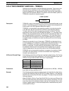
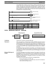
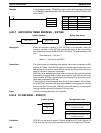
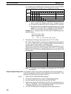
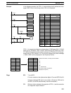
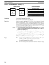
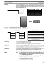
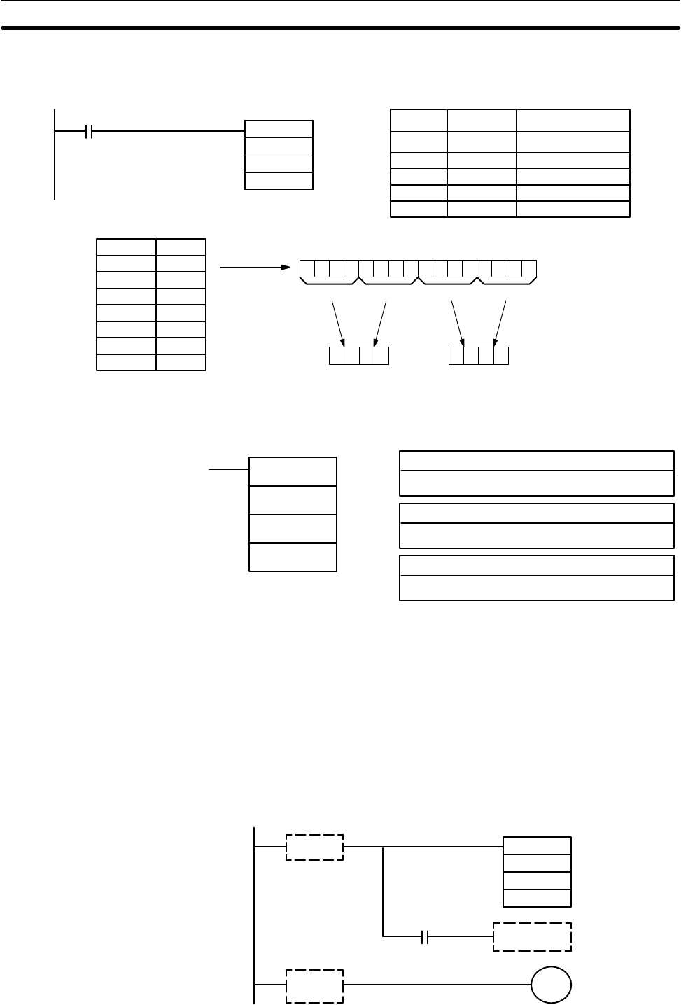
Example When IR 00000 is ON in the following example, the frame checksum (0008) is
calculated for the 8 words from DM 0000 to DM 0007 and the ASCII equivalent
(30 30 30 38) is written to DM 0011 and DM 0010.
@FCS(––)
DM 0000
#0008
00000
DM 0010
Address Instruction Operands
00000 LD 00000
00001 @FCS(––)
# 0008
DM 0000
DM 0010
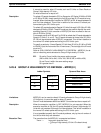
DM 0000 0001
DM 0001 0002
DM 0002 0003
DM 0003 0004
DM 0004 0005
DM 0005 0006
DM 0006 0007
DM 0007 0008
0 0 0 0 000000001000
0 800
FCS
calculation
3 0 3 8DM 00103 0 3 0DM 0011
ASCII code
conversion
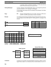
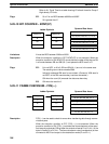
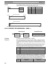
5-25-12 FAILURE POINT DETECTION – FPD(––)
T: Monitoring time (BCD)
IR, SR, AR, DM, HR, TC. LR, #
C: Control data
#
Ladder Symbols Operand Data Areas
FPD(––)
C
T
D
D: First register word
IR, AR, DM, HR, LR
Limitations D and D+8 must be in the same data area when bit 15 of C is ON.
C must be input as a constant.
Description FPD(––) can be used in the program as many times as desired, but each must
use a different D. It is used to monitor the time between the execution of FPD(––)
and the execution of a diagnostic output. If the time exceeds T, an FAL(06) non-
fatal error will be generated with the FAL number specified in C.
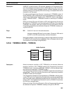
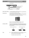
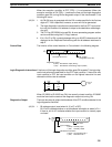
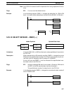
The program sections marked by dashed lines in the following diagram can be
written according to the needs of the particular program application. The proces-
sing programming section triggered by CY is optional and can used any instruc-
tions but LD and LD NOT. The logic diagnostic instructions and execution condi-
tion can consist of any combination of NC or NO conditions desired.
SR 25504
(CY Flag)
FPD(––)
T
C
D
Processing after
error detection.
Execution
condition
Branch
Logic
diagnostic
instructions
Diagnostic
output
Special Instructions Section 5-25