428
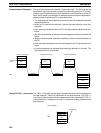
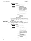
2. Use the TXD(––) instruction to transmit the data. (Bits 08 to 11 are valid only
when bits 12 to 15 are set to 0.)
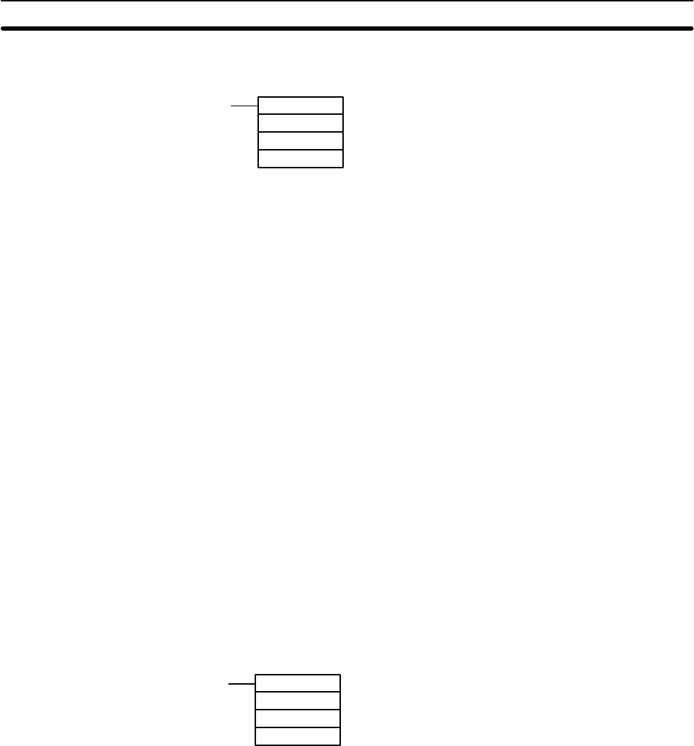
(@)TXD
S
C
N
S: Address of first word of data to be transmitted
C: Control data
Bits 00 to 03
0: Leftmost bytes first
1: Rightmost bytes first
Bits 04 to 07
0: Normal data transmission operation
1: Status of bit 15 for the leftmost word of
the transmission data is reflected on the
RTS of the corresponding port.
2: Status of bit 15 for the leftmost word of
the transmission data is reflected on the
DTR of the corresponding port.
3: Statuses of bits 14 and 15 for the
leftmost word of the transmission data are
reflected on the RTS and DTR of the
corresponding port.
Bits 08 to 11
0: Built-in RS-232C port
1: Communications Board port A
2: Communications Board port B
Bits 12 to 15
0: RS-232C port
1: Peripheral port
2: Host Link Unit #1
3: Host Link Unit #2
N: Number of bytes to be transmitted (4 digits BCD), 0000 to
0256 (start and end bits)
3. From the time this instruction is executed until the data transmission is com-
plete, the Transmit Ready Flag (SR 26405, SR 26413, SR 28305, or
SR 28313) will remain OFF. It will turn ON again upon completion of the data
transmission.
Reception (RXD(––)) Refer to 5-27-1 RECEIVE – RXD(––) for more details.
1, 2, 3... 1. Check to see that SR 26406 (RS-232C Port Reception Completed Flag) or
SR 26414 (Peripheral Port Reception Completed Flag) is ON.
2. Use the RXD(––) instruction to receive the data. (Bits 08 to 11 are valid only
when bits 12 to 15 are set to 0.)
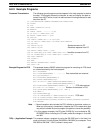
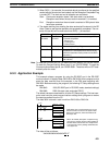
(@)RXD
D
C
N
D: Leading word no. for storing reception data
C: Control data
Bits 00 to 03
0: Leftmost bytes first
1: Rightmost bytes first
Bits 04 to 07
0: Normal data reception operation
1: Reads the status of CTS of the
corresponding port into bit 15 for the
leftmost word of the reception data write.
2: Reads the status of DSR of the
corresponding port into bit 15 for the
leftmost word of the reception data write.
3: Reads the statuses of CTS and DSR of
the corresponding port into bits 14 and 15
for the leftmost word of the reception data
write.
Bits 08 to 11
0: Built-in RS-232C port
1: Communications Board port A
2: Communications Board port B
Bits 12 to 15
0: RS-232C port
1: Peripheral port
N: Number of bytes stored (4 digits BCD), 0000 to 0256 (start
and end bits)
RS-232C Communications
Section 8-3


