


35
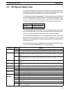
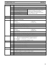
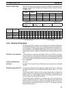
Word(s) FunctionBit(s)
255
00 0.1-second clock pulse bit
01 0.2-second clock pulse bit
02 1.0-second clock pulse bit
03 Instruction Execution Error (ER) Flag
These flags are turned OFF when the END(01)
04 Carry (CY) Flag
instruction is executed, so their status can’t be
05 Greater Than (GR) Flag
monitored from a Programming Console.
06 Equals (EQ) Flag
Refer to Appendix C for a table showing which
07 Less Than (LE) Flag
instructions affect these flags.
08 to 15 Reserved by system (used for TR bits)
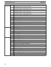
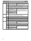
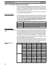
256 to 261 00 to 15 Reserved by system
262 00 to 15 Longest interrupt subroutine (action) execution time (0.1-ms units)
263 00 to 15 Number of interrupt subroutine (action) with longest execution time. (8000 to 8255)
(Bit 15 is the Interrupt Flag)
264
00 to 03 RS-232C Port Error Code
0: No error
2: Framing error
1: Parity error
3: Overrun error
04 RS-232C Port Communications Error
05 RS-232C Port Send Ready Flag
06 RS-232C Port Reception Completed Flag
07 RS-232C Port Reception Overflow Flag
08 to 11 Peripheral Port Error Code in General I/O Mode
0: No error
2: Framing error
1: Parity error
3: Overrun error
12 Peripheral Port Communications Error in General I/O Mode
13 Peripheral Port Send Ready Flag in in General I/O Mode
14 Peripheral Port Reception Completed Flag in General I/O Mode
15 Peripheral Port Reception Overflow Flag in General I/O Mode
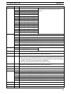
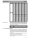
265 00 to 15 NT Link (1:N) Mode
Bits 00 to 07: Communicating with PT Flags for Units 0 to 7
Bits 08 to 15: Registering PT Priority Flags for Units 0 to 7
RS-232C Mode
Bits 00 to 15: RS-232C Port Reception Counter
266 00 to 15 Peripheral Reception Counter in RS-232C Mode
267
00 to 04 Reserved by system (not accessible by user)
05 Host Link Level 0 Send Ready Flag
06 to 12 Reserved by system (not accessible by user)
13 Host Link Level 1 Send Ready Flag
14 to 15 Reserved by system (not accessible by user)
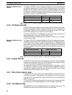
268 00 to 15 Communications Board Error Information
269
00 to 07 Memory Cassette Contents 00: Nothing; 01: UM; 02: IOM; 03: HIS
08 to 10 Memory Cassette Capacity
0: 0 KW (no cassette); 2: 4 or 8 KW; 3: 16 KW; 4: 32 KW
11 to 13 Reserved by system (not accessible by user)
14 EEPROM Memory Cassette Protected or EPROM Memory Cassette Mounted Flag
15 Memory Cassette Flag
SR (Special Relay) Area Section 3-4