


84
Both of the coding methods described above can also be used when using AND
LOAD and OR LOAD, as long as the number of blocks being combined does not
exceed eight.
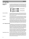
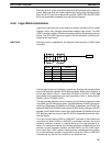
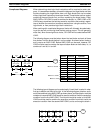
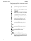
The following diagram contains only two logic blocks as shown. It is not neces-
sary to further separate block b components, because it can be coded directly
using only AND and OR.
00000 00001 00002 00003
00201
00501
00004
Block
a
Block
b
Address Instruction Operands
00000 LD 00000
00001 AND NOT 00001
00002 LD 00002
00003 AND 00003
00004 OR 00201
00005 OR 00004
00006 AND LD —
00007 OUT 00501
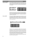
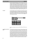
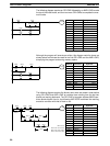
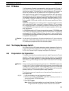
Although the following diagram is similar to the one above, block b in the diagram
below cannot be coded without separating it into two blocks combined with OR
LOAD. In this example, the three blocks have been coded first and then OR
LOAD has been used to combine the last two blocks, followed by AND LOAD to
combine the execution condition produced by the OR LOAD with the execution
condition of block a.
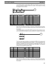
When coding the logic block instructions together at the end of the logic blocks
they are combining, they must, as shown below, be coded in reverse order, i.e.,
the logic block instruction for the last two blocks is coded first, followed by the
one to combine the execution condition resulting from the first logic block
instruction and the execution condition of the logic block third from the end, and
on back to the first logic block that is being combined.
00000 00001 00002 00003
00502
00004 00202
Block
a
Block
b
Block
b2
Block
b1
Address Instruction Operands
00000 LD NOT 00000
00001 AND 00001
00002 LD 00002
00003 AND NOT 00003
00004 LD NOT 00004
00005 AND 00202
00006 OR LD —
00007 AND LD —
00008 OUT 00502
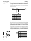
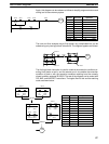
Combining AND LOAD and
OR LOAD
Basic Ladder Diagrams Section 4-4