


174
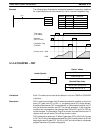
Description SFTR(84) is used to create a single- or multiple-word shift register that can shift
data to either the right or the left. To create a single-word register, designate the
same word for St and E. The control word provides the shift direction, the status
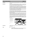
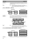
to be put into the register, the shift pulse, and the reset input. The control word is
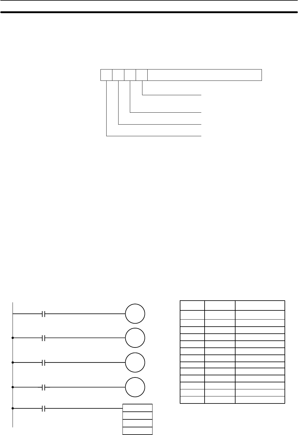
allocated as follows:
15 14 13 12 Not used.
Shift direction
1 (ON): Left (LSB to MSB)
0 (OFF): Right (MSB to LSB)
Status to input into register
Shift pulse bit
Reset
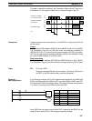
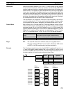
The data in the shift register will be shifted one bit in the direction indicated by bit
12, shifting one bit out to CY and the status of bit 13 into the other end whenever
SFTR(84) is executed with an ON execution condition as long as the reset bit is
OFF and as long as bit 14 is ON. If SFTR(84) is executed with an OFF execution
condition or if SFTR(84) is executed with bit 14 OFF, the shift register will remain
unchanged. If SFTR(84) is executed with an ON execution condition and the re-
set bit (bit 15) is OFF, the entire shift register and CY will be set to zero.
Flags ER: St and E are not in the same data area or ST is greater than E.
Indirectly addressed DM word is non-existent. (Content of DM word is
not BCD, or the DM area boundary has been exceeded.)
CY: Receives the status of bit 00 of St or bit 15 of E, depending on the shift
direction.
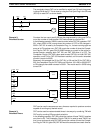
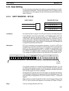
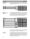
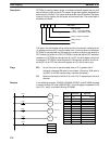
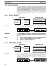
Example In the following example, IR 00005, IR 00006, IR 00007, and IR 00008 are used
to control the bits of C used in @SHIFT(84). The shift register is between LR 20
and LR 21, and it is controlled through IR 00009.
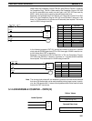
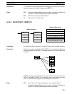
00000 LD 00005
00001 OUT 05012
00002 LD 00006
00003 OUT 05013
00004 LD 00007
00005 OUT 05014
00006 LD 00008
00007 OUT 05015
00008 LD 00009
00009 @SFT(10)
050
LR 20
LR 21
05012
00005
05013
05014
05015
00006
00007
00008
00009
Direction
Status to input
Shift pulse
Reset
@SFTR(84)
050
LR 20
LR 21
Address Instruction Operands
Data Shifting Section 5-15