


215
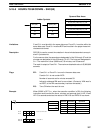
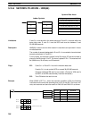
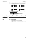
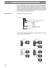
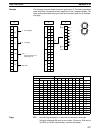
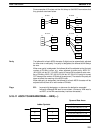
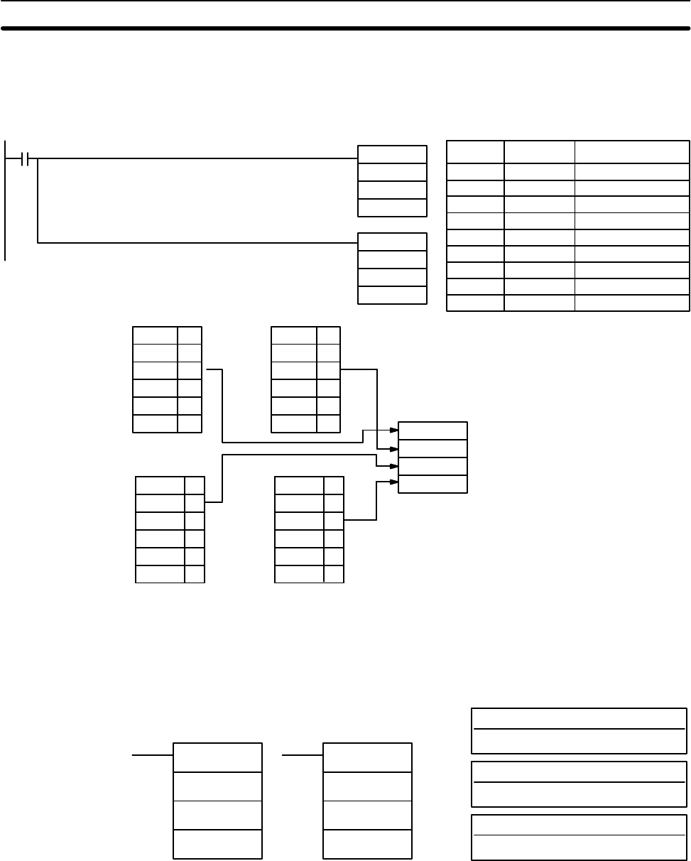
When 00000 is ON, the following diagram encodes IR words 010 and 011 to the
first two digits of HR 20 and then encodes LR 10 and 11 to the last two digits of
HR 20. Although the status of each source word bit is not shown, it is assumed
that the bit with status 1 (ON) shown is the highest bit that is ON in the word.
00000
DMPX(77)
010
HR 20
#0010
LR 10
HR 20
#0012
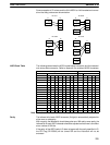
IR 010
01000
:
01011 1
01012 0
: : :
01015 0
LR 10
LR 1000
LR 1001 1
LR 1002 0
: : :
: : :
LR 1015 0
Digit 0
IR 011
01100
:
01109 1
01110 0
: : :
01115 0
Digit 1
Digit 2
Digit 3
B
9
1
8
LR 11
LR 1100
:
LR 1108 1
LR 1109 0
: : :
LR 1115 0
HR 20
DMPX(77)
Address Instruction Operands
00000 LD 00000
00001 DMPX(77)
010
HR 20
# 0010
00002 DMPX(77)
LR 10
HR 20
# 0012
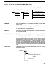
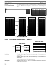
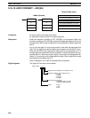
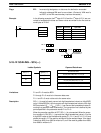
5-18-9 7-SEGMENT DECODER – SDEC(78)
S: Source word (binary)
IR, SR, AR, DM, HR, TC, LR
Di: Digit designator
IR, SR, AR, DM, HR, TC, LR, #
Ladder Symbols
Operand Data Areas
D: First destination word
IR, SR, AR, DM, HR, LR
SDEC(78)
S
Di
D
@SDEC(78)
S
Di
D
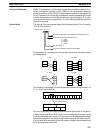
Limitations Di must be within the values given below
All destination words must be in the same data area.
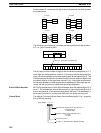
Description When the execution condition is OFF, SDEC(78) is not executed. When the
execution condition is ON, SDEC(78) converts the designated digit(s) of S into
the equivalent 8-bit, 7-segment display code and places it into the destination
word(s) beginning with D.
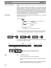
Example:
16-bit to 4-bit Encoding
Data Conversion Section 5-18