


120
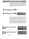
The other type of jump is created with a jump number of 00. As many jumps as
desired can be created using jump number 00 and JUMP instructions using 00
can be used consecutively without a JUMP END using 00 between them. It is
even possible for all JUMP 00 instructions to move program execution to the
same JUMP END 00, i.e., only one JUMP END 00 instruction is required for all
JUMP 00 instruction in the program. When 00 is used as the jump number for a
JUMP instruction, program execution moves to the instruction following the next
JUMP END instruction with a jump number of 00. Although, as in all jumps, no
status is changed and no instructions are executed between the JUMP 00 and
JUMP END 00 instructions, the program must search for the next JUMP END 00
instruction, producing a slightly longer execution time.
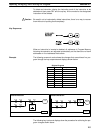
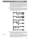
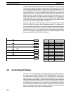
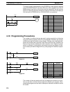
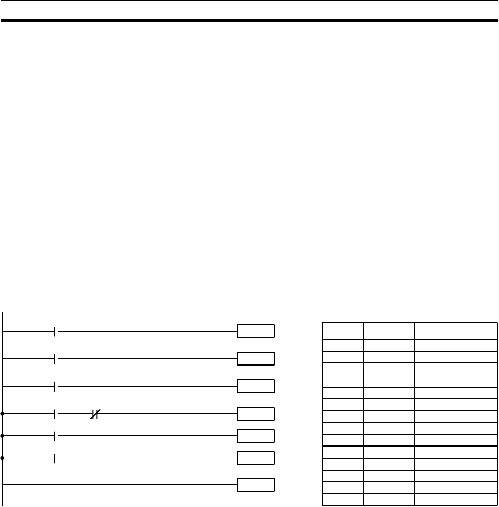
Execution of programs containing multiple JUMP 00 instructions for one JUMP
END 00 instruction is similar to that of interlocked sections. The following dia-
gram is the same as that used for the interlock example above, except redrawn
with jumps. The execution of this diagram would differ from that of the diagram
described above (e.g., in the previous diagram interlocks would reset certain
parts of the interlocked section, however, jumps do not affect the status of any bit
between the JUMP and JUMP END instructions).
Instruction 1
00000
Instruction 2
00001
JME(05) 00
JMP(04) 00
00004
Instruction 3
Instruction 4
00006
00005
00003
00002
JMP(04) 00
Address Instruction Operands
00000 LD 00000
00001 JMP(04) 00
00002 LD 00001
00003 Instruction 1
00004 LD 00002
00005 JMP(04) 00
00006 LD 00003
00007 AND NOT 00004
00008 Instruction 2
00009 LD 00005
00010 Instruction 3
00011 LD 00006
00012 Instruction 4
00013 JME(05) 00
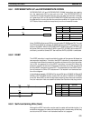
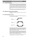
4-8 Controlling Bit Status
There are five instructions that can be used generally to control individual bit sta-
tus. These are the OUTPUT, OUTPUT NOT, DIFFERENTIATE UP, DIFFER-
ENTIATE DOWN, and KEEP instructions. All of these instructions appear as the
last instruction in an instruction line and take a bit address for an operand.
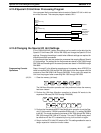
Although details are provided in 5-9 Bit Control Instructions, these instructions
(except for OUTPUT and OUTPUT NOT, which have already been introduced)
are described here because of their importance in most programs. Although
these instructions are used to turn ON and OFF output bits in the IR area (i.e., to
send or stop output signals to external devices), they are also used to control the
status of other bits in the IR area or in other data areas.
Controlling Bit Status Section 4-8