


133
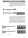
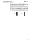
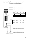
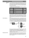
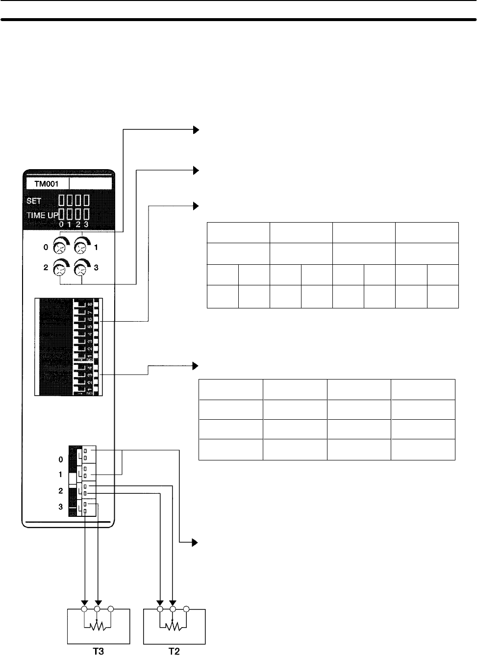
The following diagram shows the switch settings and wiring connections
required to achieve the Unit configuration shown above.
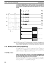
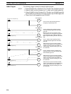
The settings on these two variable resistor controls are valid
because timers 0 and 1 are set for internal SV settings.
Use the screwdriver included with the Unit to set the variable
resistor.
The settings on these two variable resistor controls are not
valid because timers 2 and 3 are set for external SV settings.
Do not connect anything to these connectors. Timers 0 and 1
are set for internal SV settings, so the variable resistor con-
trols at the top of the Unit are used to set their SVs.
External SV Settings (0 to 20 KΩ)
Connect variable resistor for timers 2 and 3 to these connec-
tors. Refer to the Analog Timer Unit’s Operation Manual for
details on these settings.
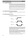
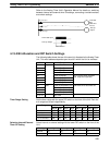
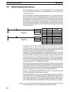
Pin 8
OFF
Pin 7
OFF
Timer 0:
0.1 to 1 second
Pin 6
ON
Pin 5
OFF
Timer 1:
1 to 10 seconds
Pin 4
OFF
Pin 3
ON
Timer 2:
10 to 60 seconds
Pin 2
ON
Pin 1
ON
Timer 3:
1 to 10 minutes
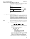
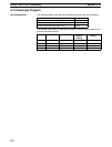
External
External
Timer 2
OFF
Pin 2
Timer 3
OFF
Pin 1
Timer 1
ON
Internal
Pin 3
Timer 0
ON
Internal
Pin 4
The timer range settings are as follows:
The internal/external SV settings are as follows:
Unit Settings and Wiring
Analog Timer Unit Programming Section 4-13