


163
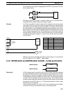
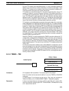
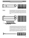
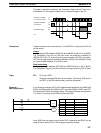
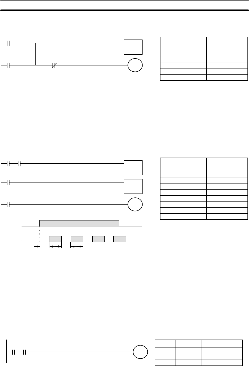
The following one-shot timer may be used to save memory.
00000
TIM 001
00100
00100
001.5 s
TIM 001
#0015
Address Instruction Operands
00000 LD 00000
00001 OR 00100
00002 TIM 001
# 0015
00003 AND NOT TIM 001
00004 OUT 00100
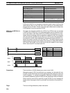
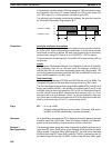
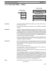
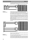
Bits can be programmed to turn ON and OFF at regular intervals while a desig-
nated execution condition is ON by using TIM twice. One TIM functions to turn
ON and OFF a specified bit, i.e., the Completion Flag of this TIM turns the speci-
fied bit ON and OFF. The other TIM functions to control the operation of the first
TIM, i.e., when the first TIM’s Completion Flag goes ON, the second TIM is
started and when the second TIM’s Completion Flag goes ON, the first TIM is
started.
00000
TIM 002
TIM 001
TIM 001
00205
00000
00205
1.5 s
1.0 s
1.5 s
1.0 s 1.5 s1.0 s
TIM 001
#0010
TIM 002
#0015
Address Instruction Operands
00000 LD 00000
00001 AND TIM 002
00002 TIM 001
# 0010
00003 LD TIM 001
00004 TIM 002
# 0015
00005 LD TIM 001
00006 OUT 00205
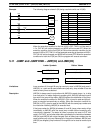
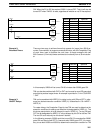
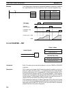
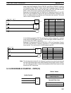
A simpler but less flexible method of creating a flicker bit is to AND one of the SR
area clock pulse bits with the execution condition that is to be ON when the flick-
er bit is operating. Although this method does not use TIM, it is included here for
comparison. This method is more limited because the ON and OFF times must
be the same and they depend on the clock pulse bits available in the SR area.
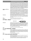
In the following example the 1-second clock pulse is used (25502) so that 00206
would be turned ON and OFF every second, i.e., it would be ON for 0.5 seconds
and OFF for 0.5 seconds. Precise timing and the initial status of 00206 would
depend on the status of the clock pulse when 00000 goes ON.
00000 25502
00206
Address Instruction Operands
00000 LD 00000
00001 AND 25502
00002 OUT 00206
Example 5:
Flicker Bits
Timer and Counter Instructions Section 5-14