


39
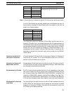
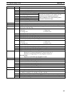
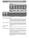
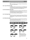
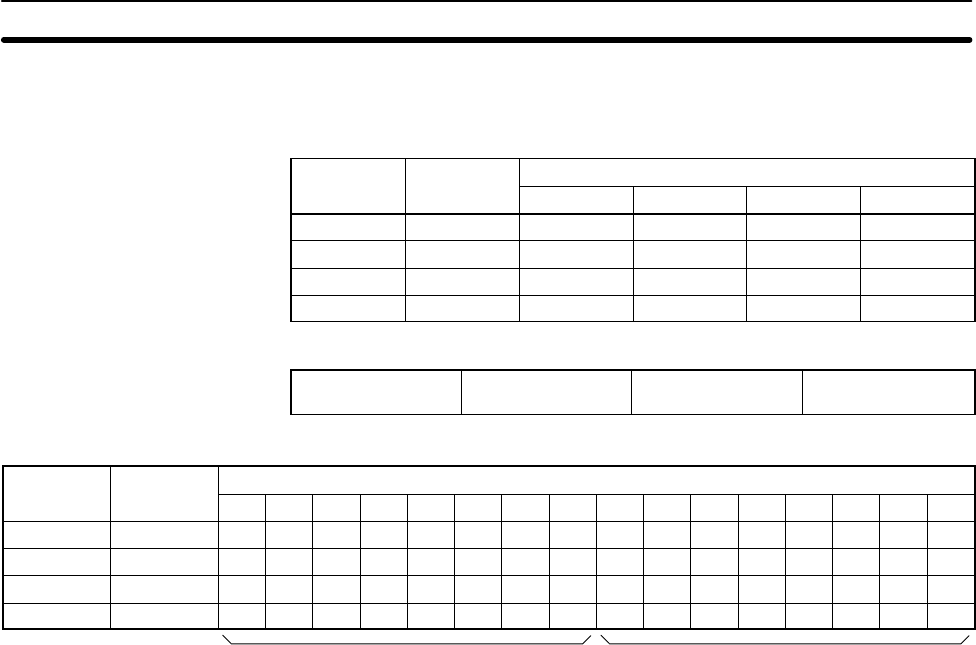
Data Link Status Flags SR 238 to SR 245 contain the data link status for SYSMAC LINK/SYSMAC NET
Systems. The data structure depends on the system used to create the data link.
SYSMAC LINK
Operating Operating
Bit
level 0 level 1
12 to 15 11 to 08 04 to 07 00 to 03
SR 238 SR 242 Node 4 Node 3 Node 2 Node 1
SR 239 SR 243 Node 8 Node 7 Node 6 Node 5
SR 240 SR 244 Node 12 Node 11 Node 10 Node 9
SR 241 SR 245 Node 16 Node 15 Node 14 Node 13
Leftmost bit Rightmost bit
1: Data link
operating
1: Communica-
tions error
1: PC CPU Unit
error
1: PC RUN status
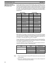
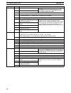
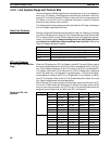
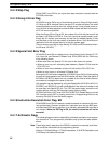
SYSMAC NET
Operating Operating
Bit (Node numbers below)
level 0 level 1
15 14 13 12 11 10 09 08 07 06 05 04 03 02 01 00
SR 238 SR 242 8 7 6 5 4 3 2 1 8 7 6 5 4 3 2 1
SR 239 SR 243 16 15 14 13 12 11 10 9 16 15 14 13 12 11 10 9
SR 240 SR 244 24 23 22 21 20 19 18 17 24 23 22 21 20 19 18 17
SR 241 SR 245 32 31 30 29 28 27 26 25 32 31 30 29 28 27 26 25
1: PC CPU Unit error 1: PC RUN status
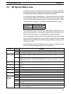
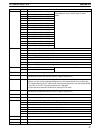
3-4-2 Remote I/O Systems
SR 25312 turns ON to indicate an error has occurred in Remote I/O Systems.
The ALM/ERR indicator will flash, but PC operation will continue. SR 251 con-
tains information on the source and type of error and AR 0014 and AR 0015 con-
tain information on the SYSMAC LINK status. The function of each bit is de-
scribed below. Refer to Optical and Wired Remote I/O System Manuals for de-
tails.
SR 25100 – Error Check Bit If there are errors in more than one Remote I/O Unit, word SR 251 will contain
error information for only the first one. Data for the remaining Units will be stored
in memory and can be accessed by turning the Error Check bit ON and OFF. Be
sure to record data for the first error, which will be cleared when data for the next
error is displayed.
SR 25101 and SR 25102 Not used.
SR 25103 Remote I/O Error Flag: Bit 03 turns ON when an error has occurred in a Remote
I/O Unit.
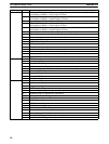
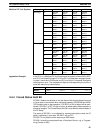
SR 25104 through SR 25115 The content of bits 04 to 06 is a 3-digit binary number (04: 2
0
, 05: 2
1
, 06: 2
2
) and
the content of bits 08 to 15 is a 2-digit hexadecimal number (08 to 11: 16
0
, 12 to
15: 16
1
).
If the content of bits 12 through 15 is B, an error has occurred in a Remote I/O
Master or Slave Unit, and the content of bits 08 through 11 will indicate the unit
number, either 0 or 1, of the Master involved. In this case, bits 04 to 06 contain
the unit number of the Slave Rack involved.
If the content of bits 12 through 15 is a number from 0 to 31, an error has oc-
curred in an Optical I/O Unit or I/O Terminal. The number is the unit number of the
Optical I/O Unit or I/O Terminal involved, and bit 04 will be ON if the Unit is as-
signed leftmost word bits (08 through 15), and OFF if it is assigned rightmost
word bits (00 through 07).
SR (Special Relay) Area Section 3-4