


20
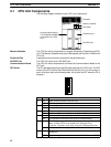
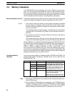
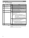
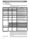
2-5 CPU Unit DIP Switch
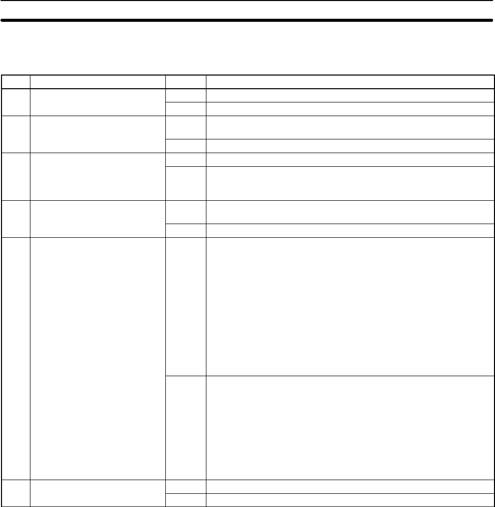
The 6 pins on the DIP switch control 6 of the CPU Unit’s operating parameters.
Pin Item Setting Function
1 Memory protect
ON The UM area
1
cannot be overwritten from a Peripheral Device.
OFF The UM area
1
can be overwritten from a Peripheral Device.
2 Automatic transfer of Memory
Cassette contents
ON The contents of the Memory Cassette will be automatically
transferred to the internal RAM at start-up.
OFF The contents will not be automatically transferred.
3 Message language
ON Programming Console messages will be displayed in English.
OFF Programming Console messages will be displayed in the language
stored in system ROM. (Messages will be displayed in Japanese with
the Japanese version of system ROM.)
4 Expansion instruction setting
ON Expansion instructions will be set by user. Normally ON when using a
host computer for programming/monitoring.
OFF Expansion instructions will be set to defaults.
5 Communications parameters
ON Standard communications parameters (see note 1) will be set for the
following serial communications ports.
• Built-in RS-232C port
• Peripheral port (only when a CQM1-CIF01/-CIF02 Cable is con-
nected. Does not apply to Programming Console.)
Note 1. Standard communications parameters are as follows:
Serial communications mode: Host Link or peripheral bus;
start bits: 1; data length: 7 bits; parity: even; stop bits: 2;
baud rate: 9,600 bps
2. The CX-Programmer running on a personal computer can
be connected to the peripheral port via the peripheral bus
using the above standard communications parameters.
OFF The communications parameters for the following serial
communications ports will be set in PC Setup as follows:
• Built-in RS-232C port: DM 6645 and DM 6646
• Peripheral port: DM 6650 and DM 6651
Note When the CX-Programmer is connected to the peripheral port
with the peripheral bus, either set bits 00 to 03 of DM 6650 in the
Fixed DM Area to 0 Hex (for standard parameters), or set bits 12
to 15 of DM 6650 to 0 Hex and bits 00 to 03 of DM 6650 to 1 Hex
(for Host Link or peripheral bus ) separately.
6 Expansion TERMINAL mode
ON Expansion TERMINAL mode (Programming Console); AR 0712 ON.
setting when AR 0712 is ON
OFF Normal mode (Programming Console); AR 0712: OFF
Note 1. The UM area contains the ladder program, fixed DM (including the PC Set-
up), expansion DM, I/O comments, the I/O table, and the UM area allocation
information.
2. All six pins are set to OFF when the PC is shipped.
CPU Unit DIP Switch Section 2-5