


420
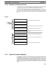
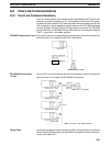
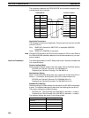
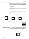
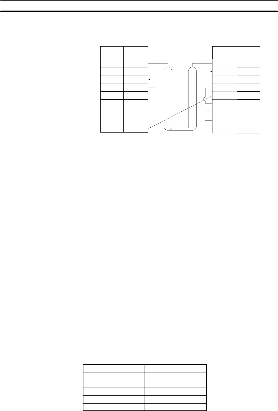
The connections between the C200HX/HG/HE and a personal computer are il-
lustrated below as an example.
1
2
3
4
5
6
FG
SD
RD
RS
CS
–
–
–
SG
7
8
9
1
2
3
4
5
6
7
8
9
SD
RD
RS
CS
DSR
SG
–
9
DTR
C200HX/HG/HE Personal computer
SignalPin
No.
Signal Pin
No.
Shielded cable
–
Applicable Connectors
The following connectors are applicable. One plug and one hood are included
with the CPU Unit.
Plug: XM2D-0901 (female) for IBM PC/AT or compatible (OMRON)
or equivalent
Hood: XM2S-0911 (OMRON) or equivalent
Note Ground the FG terminal on the PC and at the computer to 100 Ω or less. Refer to
the C200HX/HG/HE Installation Manual and to the documentation for your com-
puter for details.
Host Link Parameters The following parameters in the PC Setup must be set in advance to enable Host
Link communications.
Communications Mode
Set the communications mode to Host Link mode. (This is the default setting.)
RS-232C port: Set bits 12 through 15 of DM 6645 to 0.
Peripheral port: Set bits 12 through 15 of DM 6650 to 0.
Node Number Setting
When 1:N connections are being used, set a unique node number from 00 to 31.
When a 1:1 connection is being used, set the PC’s node number to 00.
RS-232C port: Set bits 00 through 07 of DM 6648 (00 to 31).
Peripheral port: Set bits 00 through 07 of DM 6653 (00 to 31).
Standard Port Settings
Standard settings or custom settings can be used for the RS-232C and peripher-
al ports. The standard settings are used when the following bits are set to 0.
(The custom settings are explained below.)
RS-232C port: Bits 00 through 03 of DM 6645 (0: standard; 1: custom).
Peripheral port: Bits 00 through 03 of DM 6650 (0: standard; 1: custom).
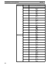
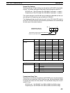
The standard settings are shown in the following table.
Item Setting
Start bits 1
Data length 7
Stop bits 2
Parity Even
Baud rate 9,600 bps
Host Link Communications
Section 8-2