68
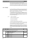
Setting FunctionMode
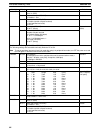
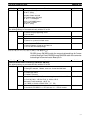
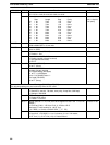
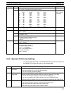
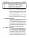
11 C200H-compatible
ROM Mode 2
The contents of DM 7000 through DM 8599 are transferred to DM 1000 through DM 2599
at startup and DM 1000 through DM 2599 are used for the Special I/O Unit Area.
• The UM Area Allocation operation must be performed beforehand.
• ROM conversion is possible indirectly by converting DM 7000 through DM 8599 to ROM.
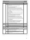
12 DM Linear Mode 2 DM 7000 through DM 8599 are used for the Special I/O Unit Area.
• The UM Area Allocation operation must be performed beforehand.
• DM 1000 through DM 2599 can be used as regular DM.
• DM 7000 through DM 8599 can be converted to ROM.
DM 7000 through DM 9999 cannot be read or overwritten directly from the pro-
gram. To read this data from the program, the data must be copied to another
data area or regular DM using the EXPANSION DM READ – XDMR(––) instruc-
tion.
When C200H-compatible ROM Mode or DM Linear Mode is set, the UM Area
Allocation operation must be performed in advance to allocate part of the ladder
program area for use as expansion DM. A system error (FAL 9B) will occur if
memory isn’t allocated as expansion DM. Refer to 7-2-15 UM Area Allocation for
details on the UM Area Allocation operation.
When DM Linear Mode is set, the Special I/O Unit’s data area will begin from
DM 7000 instead of DM 1000 so add 6000 to the DM addresses where they ap-
pear in the Special I/O Unit’s Operation Manual.
When the Special I/O Unit Area setting is 01, 02, 11, or 12 and expansion DM
beyond DM 8000 hasn’t been allocated, a Special I/O Unit error will occur for a
Unit with unit number A through F when the Unit accesses its allocated area.
3-7 HR (Holding Relay) Area
The HR area is used to store/manipulate various kinds of data and can be ac-
cessed either by word or by bit. Word addresses range from HR 00 through HR
99; bit addresses, from HR 0000 through HR 9915. HR bits can be used in any
order required and can be programmed as often as required.
The HR area retains status when the system operating mode is changed, when
power is interrupted, or when PC operation is stopped.
HR area bits and words can be used to preserve data whenever PC operation is
stopped. HR bits also have various special applications, such as creating latch-
ing relays with the Keep instruction and forming self-holding outputs. These are
discussed in Section 4 Writing and Inputting the Program and Section 5 Instruc-
tion Set.
Note The required number of words is allocated between HR 00 and HR 42 for routing
tables and to monitor timers when using SYSMAC NET Systems.
3-8 TC (Timer/Counter) Area
The TC area is used to create and program timers and counters and holds the
Completion flags, set values (SV), and present values (PV) for all timers and
counters. All of these are accessed through TC numbers ranging from TC 000
through TC 511. Each TC number is defined as either a timer or counter using
one of the following instructions: TIM, TIMH, CNT, CNTR(12), and TTIM(87). No
prefix is required when using a TC number in a timer or counter instruction.
Once a TC number has been defined using one of these instructions, it cannot
be redefined elsewhere in the program either using the same or a different
instruction. If the same TC number is defined in more than one of these instruc-
tions or in the same instruction twice, an error will be generated during the pro-
gram check. There are no restrictions on the order in which TC numbers can be
used.
TC (Timer/Counter) Area Section 3-8


