


134
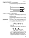
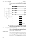
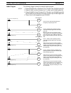
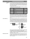
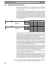
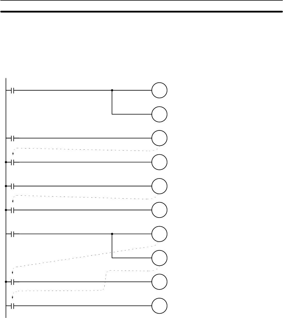
The following diagram shows the example ladder program.
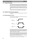
1, 2, 3... 1. Output IR 00500 will go ON about 0.6 s (T0) after input IR 00002 goes ON.
2. Output IR 00501 will go ON about 3 s (T1) after input IR 00003 goes ON.
3. Output IR 00502 will go ON about 20 s (T2) after input IR 00004 goes ON
and IR 00503 will go ON about 8 minutes (T3) after input IR 00004 goes ON.
4. Timers 2 and 3 are stopped by input IR 00005.
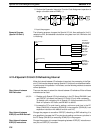
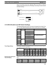
When the time set on the internal variable
resistor control elapses, the Completion Flag
(00209) goes ON and the Unit’s TIME UP
indicator lights. Output IR 00501 goes ON at
the same time.
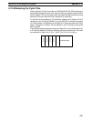
When the time set on the external variable
resistor control elapses, the Completion Flag
(00210) goes ON and the Unit’s TIME UP
indicator lights. Output IR 00502 goes ON at
the same time.
When the time set on the external variable
resistor control elapses, the Completion Flag
(00211) goes ON and the Unit’s TIME UP
indicator lights. Output IR 00503 goes ON at
the same time.
00206
00207
00200
00202
00203
00501
00500
00201
00502
00503
00005
00002
00004
00209
00208
00003
00210
00211
Timers 2 and 3 stop operating when the
emergency stop input goes ON.
When the time set on the internal volume
control elapses, the Completion Flag (00208)
goes ON and the Unit’s TIME UP indicator
lights. Output IR 00500 goes ON at the same
time.
Timer 0 (00200) starts operating and the
Unit’s SET indicator lights when IR 00002
goes ON.
Timer 1 (00201) starts operating and the
Unit’s SET indicator lights when IR 00003
goes ON.
Timer 2 (00202) and timer 3 (00203) start
operating and the Unit’s SET indicator lights
when IR 00004 goes ON.
Timer Stop Bit
Timer 0 Set Bit
Timer 1 Set Bit
Timer 2 Set Bit
T2
T3
T0
T1
T2
T3
Timer 0 Completion Flag
Timer 1 Completion Flag
Timer 2 Completion Flag
Timer 3 Completion Flag
Timer 0 Completion Flag
Ladder Program
Analog Timer Unit Programming Section 4-13