


166
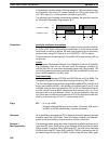
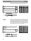
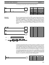
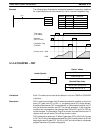
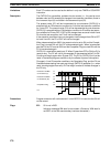
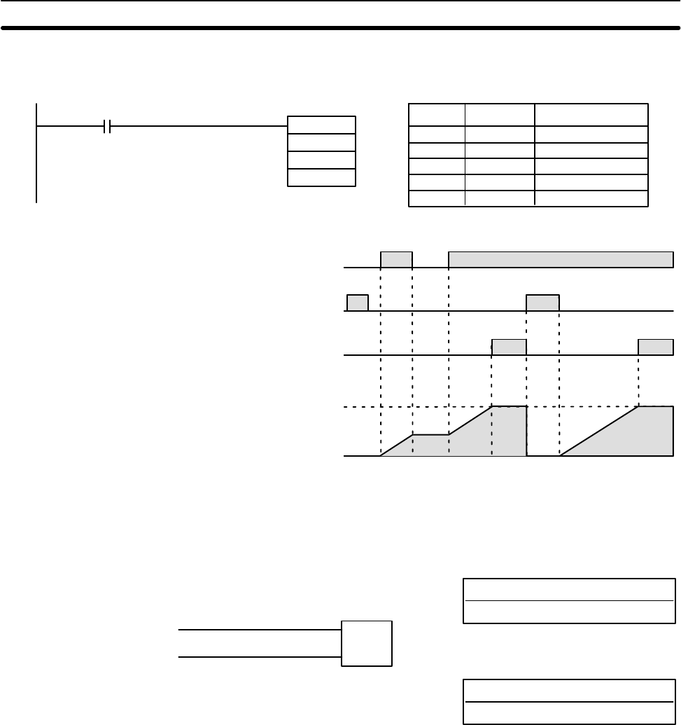
Example The following figure illustrates the relationship between the execution conditions
for a totalizing timer with a set value of 2 s, its PV, and the Completion Flag.
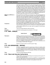
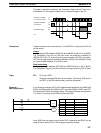
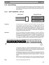
Address Instruction Operands
00000 LD 00000
00001 TTIM(87)
TIM 000
# 0020
LR 2100
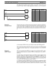
00000
TTIM(87)
TIM 000
#0020
LR 2100
Timer input
(I: IR 00000)
Reset bit
(RB: LR 2100)
Completion Flag
(TIM 000)
Present value: 0020
0000
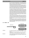
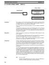
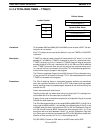
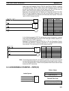
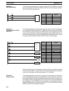
5-14-4 COUNTER – CNT
N: TC number
# (000 through 511)
Ladder Symbol
Definer Values
SV: Set value (word, BCD)
IR, AR, DM, HR, LR, #
Operand Data Areas
CP
R
CNT N
SV
Limitations Each TC number can be used as the definer in only one TIMER or COUNTER
instruction.
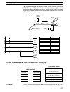
Description CNT is used to count down from SV when the execution condition on the count
pulse, CP, goes from OFF to ON, i.e., the present value (PV) will be decrem-
ented by one whenever CNT is executed with an ON execution condition for CP
and the execution condition was OFF for the last execution. If the execution
condition has not changed or has changed from ON to OFF, the PV of CNT will
not be changed. The Completion Flag for a counter is turned ON when the PV
reaches zero and will remain ON until the counter is reset.
CNT is reset with a reset input, R. When R goes from OFF to ON, the PV is reset
to SV. The PV will not be decremented while R is ON. Counting down from SV will
begin again when R goes OFF. The PV for CNT will not be reset in interlocked
program sections or by power interruptions.
Timer and Counter Instructions Section 5-14