


153
5-9-3 SET and RESET – SET and RSET
B: Bit
IR, SR, AR, HR, LR
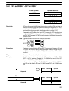
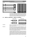
Ladder Symbols Operand Data Areas
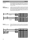
SET B
B: Bit
IR, SR, AR, HR, LR
RSET B
Description SET turns the operand bit ON when the execution condition is ON, and does not
affect the status of the operand bit when the execution condition is OFF. RSET
turns the operand bit OFF when the execution condition is ON, and does not af-
fect the status of the operand bit when the execution condition is OFF.
The operation of SET differs from that of OUT because the OUT instruction turns
the operand bit OFF when its execution condition is OFF. Likewise, RSET differs
from OUT NOT because OUT NOT turns the operand bit ON when its execution
condition is OFF.
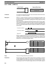
Note The instructions SET and RESET are input as follows:
SET: Operand
RESET: Operand
Precautions The status of operand bits for SET and RSET programmed between IL(02) and
ILC(03) or JMP(04) and JME(05) will not change when the interlock or jump
condition is met (i.e., when IL(02) or JMP(04) is executed with an OFF execution
condition).
Flags There are no flags affected by these instructions.
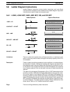
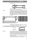
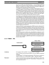
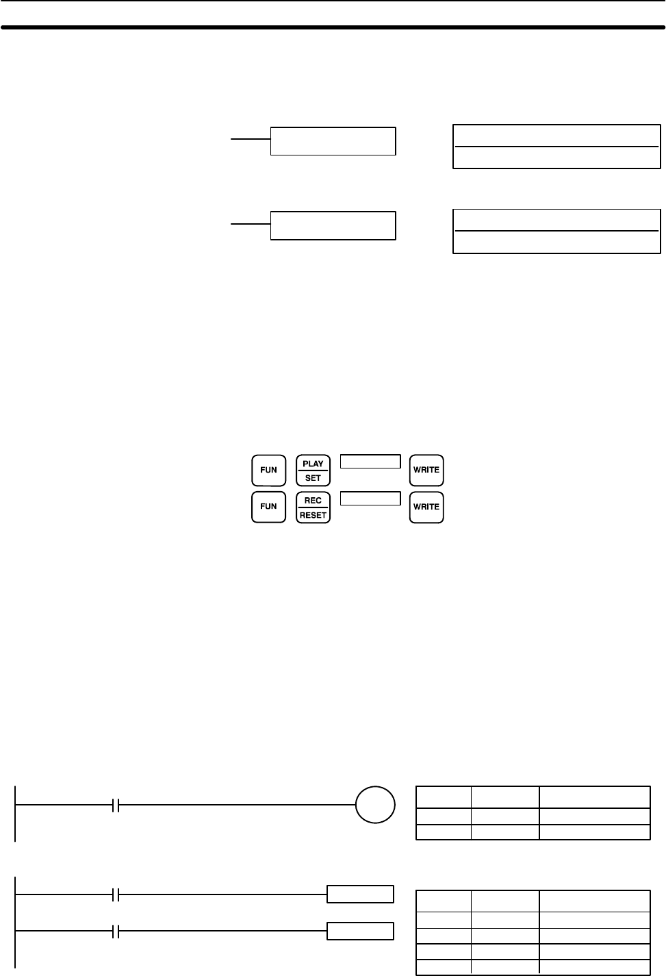
Examples The following examples demonstrate the difference between OUT and SET/
RSET. In the first example (Diagram A), IR 10000 will be turned ON or OFF
whenever IR 00000 goes ON or OFF.
In the second example (Diagram B), IR 10000 will be turned ON when IR 00001
goes ON and will remain ON (even if IR 00001 goes OFF) until IR 00002 goes
ON.
00000
Diagram A
00002
RSET 10000
Diagram B
SET 10000
00001
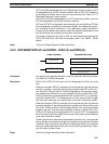
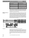
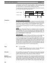
Address Instruction Operands
00000 LD 00000
00001 OUT 10000
Address Instruction Operands
00000 LD 00001
00001 SET 10000
00002 LD 00002
00003 RSET 10000
10000
Bit Control Instructions Section 5-9