349
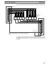
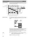
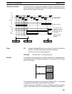
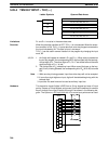
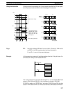
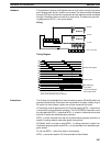
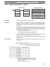
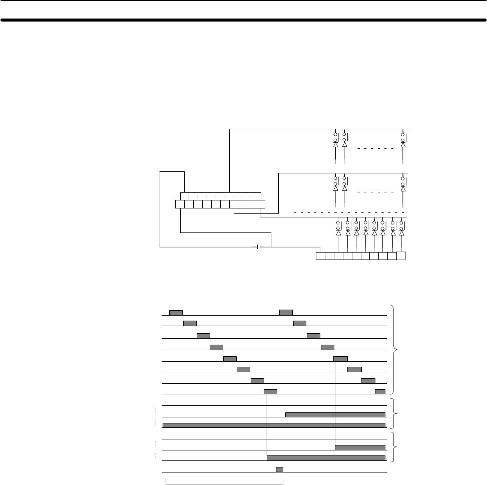
Hardware This instruction inputs up to 64 signals from an 8 x 8 matrix using 8 input points
and 8 output points. Any 8 x 8 matrix can be used. The inputs must be connected
through a DC Input Unit with 8 or more points and the outputs must be connected
through a Transistor Output Unit with 8 or more points. The basic wiring and tim-
ing diagrams for MTR(––) are shown below.
Wiring
8th row
7th row
1st row
ID 211 I/O Unit
B0B1B2B3B4B5B6B7B8B9
A0A1A2A3A4A5A6A7A8A9
A0A1A2A3A4A5A6A7A8
Timing Diagram
Matrix select signal
Matrix status
Bits indicating
input status
One-round Flag (bit
08 of output word)
Each round completed in 24 executions
00
01
02
03
04
05
06
07
00
32
64
00
32
64
06
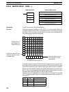
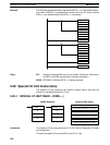
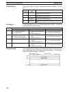
Precautions The 64 keys can be divided into 8 rows (including a row for OW bit 08) which are
scanned consecutively. Since each row is scanned for 3 cycles, a delay of up to
25 cycles can occur before a given row of keys is scanned for inputs.
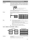
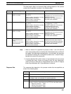
I/O refreshing must be performed for all I/O points used by MTR(––) each time it
is executed to ensure effective operation. The I/O REFRESH instruction must
thus be used with MTR(––) whenever MTR(––) is used in a subroutine to ensure
that the I/O points are refreshed each execution.
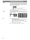
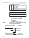
MTR(––) will be executed from the first cycle whenever program execution is
started, including restarts made after power interruptions.
SR 25403, which is turned on while MTR(––) is being executed, is reset in an
interlocked program section and MTR(––) is not executed in an interlocked pro-
gram section.
Do not use MTR(––) more than twice in the program.
MTR(––) cannot be used for I/O Units mounted to Slave Racks.
Advanced I/O Instructions Section 5-28


