


381
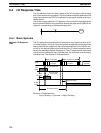
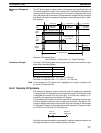
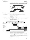
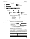
In looking at the following timing charts, it is important to remember the se-
quence processing occurs during the PC scan, particular that inputs will not pro-
duce programmed-actions until the program has been execution.
X
PC Link Unit
PC
PC Link Unit
PC
X
X
Unit 0 Unit 7
Input on PC
of Unit 0
LR
bit
Input LR XXXX
Output on PC
of Unit 7
LR XXXX
Input
Output
Output
Note Noise may increase I/O delays.
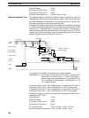
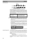
PC Link Conditions The PC Link System used in this example consists of the following:
• No. of PCs linked: 8
• No. of LR points linked: 128 per PC
• Maximum PC: 8
• LR points used: 1,024
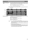
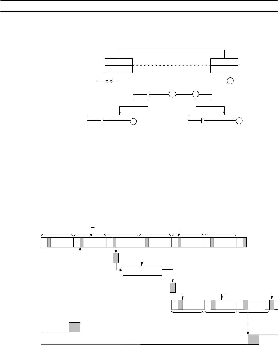
The following illustrates the data flow that will produce the minimum response
time, i.e., the time that results when all signals and data transmissions are pro-
cessed as soon as they occur.
PC with
Unit 0
Buffer in Unit 0
PC Link Unit trans-
missions
Buffer in Unit 7
Input
Output
Minimum transmission time
Program
executed.
Cycle time
Cycle time
I/O refresh
Program executed.
PC with
Unit 7
I/O refresh
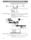
The equation for minimum I/O response time is thus as follows:
Response time = Input ON delay + Cycle time of PC of Unit 0 + Minimum trans-
mission time + (Cycle time of PC of Unit 7 × 2) + Output ON
delay
Inserting the following values into this equation produces a minimum I/O re-
sponse time of 149.3 ms.
Input ON delay: 1.5 ms
Minimum Response Time
I/O Response Time Section 6-4