


EATON Powerware
®
9315 UPS (500–750 kVA) Installation and Operation Manual S 164201244 Rev E www.powerware.com
A-1
Appendix A
Fi
g
u
r
Installation Reference
The information in this appendix will help you plan for and install the Powerware
9315. This appendix contains the following information:
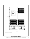
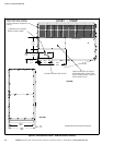
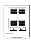
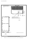
S Physical features and requirements, including dimensions
S UPS system oneline configurations
S Power wiring installation notes
S Location of UPS terminals, including the Inverter/Rectifier, Output/Inverter, and
Module Bypass Cabinets (MBCs)
S Customer interface wiring notes
S Typical remote emergency power-off (REPO)
S Remote Monitor Panel (RMP) dimensions
S Relay Interface Module (RIM) dimensions
S Supervisory Contact Module (SCM) dimensions
S Battery disconnect switch dimensions
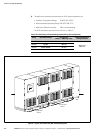
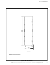
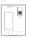
A.1 Physical Features and Requirements
1. The UPS equipment operating environment must meet the size and weight
requirements shown in Table A, according to your UPS system configuration.
2. In the UPS system, the UPS, Input/Rectifier, Output/Inverter, and MBC or
System Bypass Module (SBM) are palleted separately for shipping.
3. Do not tilt the UPS or optional cabinets more than 10° from vertical or the
cabinet may tip over.
4. Dimensions are in millimeters [inches].
Table A. Equipment Weight
Powerware 9315 Component
Weight
kg (lb)
Shipping Installed
Power Control Module (PCM) 1 (Input/Rectifier) 2818 (6200) 2682 (5900)
PCM 2 (Output/Inverter) 2909 (6400) 2773 (6100)
PCM 3 (MBC) 272.7 (600) 250 (550)
5. The clearances required around the UPS cabinet are shown in Table B.
Table B. UPS Cabinet Clearances
From the Top of the Cabinet Minimum clearance over the UPS cabinet is 30.5 cm (12”)
From the Front of the Cabinet 91.4 cm (36”) working space