


INSTALLING OPTIONAL ACCESSORIES
EATON Powerware
®
9315 UPS (500–750 kVA) Installation and Operation Manual S 164201244 Rev E www.powerware.com
6-10
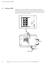
6.4 Installing X-Slot Cards
NOTE LAN and telephone drops for use with X-Slot cards must be provided by facility planners or the
customer.
NOTE For setup of an X-Slot card, please contact Eaton (see page 1-7).
To install the X-Slot cards:
1. If not already installed, install the LAN, telephone, or other cables.
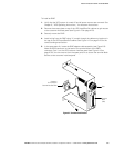
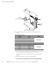
2. Remove the access plate on top of the UPS Input/Rectifier cabinet to gain access
to the customer interface panel (see Figure A‐13 on page A-23).
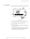
3. Remove the X-Slot cover plate to gain access to the X-Slot communication bay
(see Figure A‐19 on page A-30).
4. Install the X-Slot card into the communication bay.
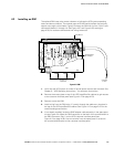
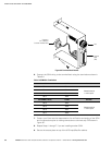
5. Route and install the LAN, telephone, and other cables to the appropriate X-Slot
card.
6. Refer to the manual supplied with the X-Slot card for operator instructions.