


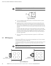

INSTALLING OPTIONAL ACCESSORIES
EATON Powerware
®
9315 UPS (500–750 kVA) Installation and Operation Manual S 164201244 Rev E www.powerware.com
6-3
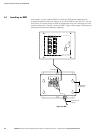
To install an RMP:
1. Verify that the UPS system is turned off and all power sources are removed. See
Chapter 9, “UPS Operating Instructions,” for shutdown instructions.
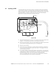
2. Remove the access plate on top of the UPS Input/Rectifier cabinet to gain access
to the customer interface panel (see Figure A‐13 on page A-23).
3. Securely mount the RMP.
4. Install wiring from the RMP using ½” conduit through the cable entry knockout in
the top of the UPS Input/Rectifier cabinet. See Figure A‐13 on page A-23 for the
conduit landing area location.
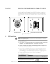
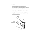
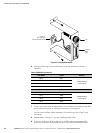
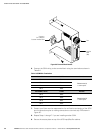
5. In the spare parts kit, locate the RMP adapter cable assembly (see Figure 6‐2).
Mate the DB‐9 connector on the back of the terminal block to the DB‐9
connector (Port 1) on the UPS customer interface panel (see Figure A‐19 on
page A-30). Use two screws from the spare parts kit to secure the terminal block
bracket to the customer interface panel.
Connect to
Port 1 (DB‐9) on
Customer Interface Panel
Fuse
Terminal
Block
(TB3)
Figure 6‐2. Terminal Block Bracket