


INSTALLATION REFERENCE
EATON Powerware
®
9315 UPS (500–750 kVA) Installation and Operation Manual S 164201244 Rev E www.powerware.com
A-19
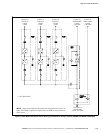
14. External overcurrent protection is not provided by this product, but is required
by codes. See Table E through Table G starting on page A-13 for wiring
requirements. If an output lockable disconnect is required, it is to be supplied
by designated personnel.
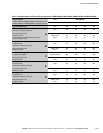
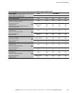
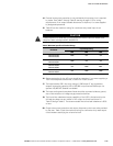
15. Table K lists the maximum rating for continuous duty rated input circuit
breakers.
C A U T I O N
To reduce the risk of fire, connect only to a circuit provided with maximum input circuit breaker current
ratings from Table K according to the NEC, ANSI/NFPA 70.
Table K. Maximum Input Circuit Breaker Ratings
UPS Model
Input Voltage Rating
400V 480V 600V
PW9315-625/400
PW9315-625/450
1000A N/A N/A
PW9315-625/500
PW9315-625/562
1200A N/A N/A
PW9315-750/500
PW9315-750/562
N/A 1000A 800A
PW9315-750/600
PW9315-750/675
N/A 1200A 1000A
16. Source protection for the AC input should be treated as if you were supplying a
750 kVA three-phase transformer, to allow for inrush current.
17. The input breaker (CB1) has a trip rating of 1200 amps AT and a standard
ampere interrupting capacity (AIC) of 65,000 in symmetrical RMS amps. An
optional 100,000 AIC breaker is available.
18. The input and bypass three-phase feeds should be symmetrical about ground,
due to the existence of voltage surge protection devices.
19. The line‐to‐line unbalanced output capability of the UPS is limited only by the
full load per phase current values for AC output to critical load shown in
Table E through Table G. The recommended line‐to‐line load unbalance is 50%
or less.
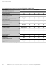
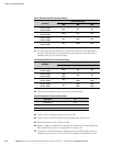
20. Output overcurrent protection and output disconnect switch are to be provided
by the user. Table L lists the maximum rating for continuous duty rated output
circuit breakers satisfying the criteria for both.