


INSTALLATION REFERENCE
EATON Powerware
®
9315 UPS (500–750 kVA) Installation and Operation Manual S 164201244 Rev E www.powerware.com
A-32
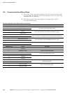
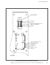
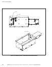
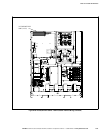
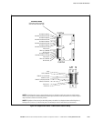
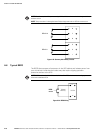
Table P. Output/Inverter Cabinet Customer Interface Connections
CUSTJ4 Terminal Name Description
1
Building Alarm 2
Programmable UPS alarm. Activated by a remote dry contact closure.
2 Building Alarm 2 Return
3 Building Alarm 3
Programmable UPS alarm. Activated by a remote dry contact closure.
4 Building Alarm 3 Return
5 Building Alarm 4
Programmable UPS alarm. Activated by a remote dry contact closure.
6 Building Alarm 4 Return
7 Building Alarm 5
Programmable UPS alarm. Activated by a remote dry contact closure.
8 Building Alarm 5 Return
9 Not Used
10 Not Used
CUSTJ2 Terminal Name Description
1 Relay 1 NC
General purpose normally‐open and normally‐closed relay contacts.
2 Relay 1 Commom
3 Relay 1 NO
4 Building Alarm 1
Programmable UPS alarm. Activated by a remote dry contact closure.
5 Building Alarm 1 Return
6 Relay 2 NC
General purpose normally‐open and normally‐closed relay contacts.
7 Relay 2 Common
8 Relay 2 NO
9 Not Used
10 Not Used
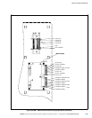
CUSTTB Terminal Name Description
1 CB3 - Aux #2
Circuit breaker CB3 auxiliary contact.
2 CB3 - Aux #2*
3 Not Used
4 Remote to Bypass
Dry contact used to activate remote transfer to bypass.
5 Remote to Bypass Return
6 Remote to UPS
Dry contact used to activate remote transfer to UPS.
7 Remote to UPS Return
8 Not Used
9 REPO
Dry contact used to activate REPO of UPS.
10 REPO Common