


INSTALLATION REFERENCE
EATON Powerware
®
9315 UPS (500–750 kVA) Installation and Operation Manual S 164201244 Rev E www.powerware.com
A-20
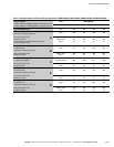
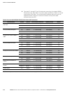
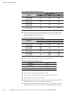
Table L. Maximum Output Circuit Breaker Ratings
UPS Model
Output Voltage Rating
400V 480V 600V
PW9315-625/400
PW9315-625/450
800A N/A N/A
PW9315-625/500
PW9315-625/562
1000A N/A N/A
PW9315-750/500
PW9315-750/562
N/A 800A 700A
PW9315-750/600
PW9315-750/675
N/A 1000A 800A
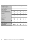
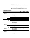
21. DC input overcurrent protection and disconnect switch are to be provided by
the user. Table M lists the maximum rating for continuous duty rated circuit
breakers satisfying the criteria for both.
Table M. Maximum DC Input Circuit Breaker Ratings
UPS Model
Output Voltage Rating
400V 480V 600V
PW9315-625/400
PW9315-625/450
1600A N/A N/A
PW9315-625/500
PW9315-625/562
1800A
2000A
N/A N/A
PW9315-750/500
PW9315-750/562
N/A
1800A
2000A
1800A
2000A
PW9315-750/600
PW9315-750/675
N/A
2000A
2300A
2000A
2300A
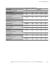
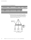
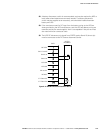
22. Table N lists the battery shunt trip trip wiring requirements.
Table N. Battery Shunt Trip Wiring Requirements
Description ST
CB2TB Points 9, 10
Output Max Pulse 220 VA instantaneous
Wiring #18 AWG minimum
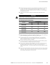
23. There is no DC disconnect device within the UPS.
24. The DC input to the UPS is protected by internal fuses F30 and F31.
25. Recommended wire size is #18–14 AWG.
26. Battery voltage is computed at 2 volts per cell as defined by Article 480 of the
NEC. Rated battery current is computed at 2 volts per cell.
27. The battery wiring used between the battery and the UPS should not allow a
voltage drop of more than 1% of nominal DC voltage at rated battery current.