


INSTALLATION REFERENCE
EATON Powerware
®
9315 UPS (500–750 kVA) Installation and Operation Manual S 164201244 Rev E www.powerware.com
A-33
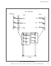
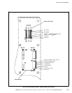
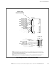
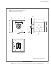
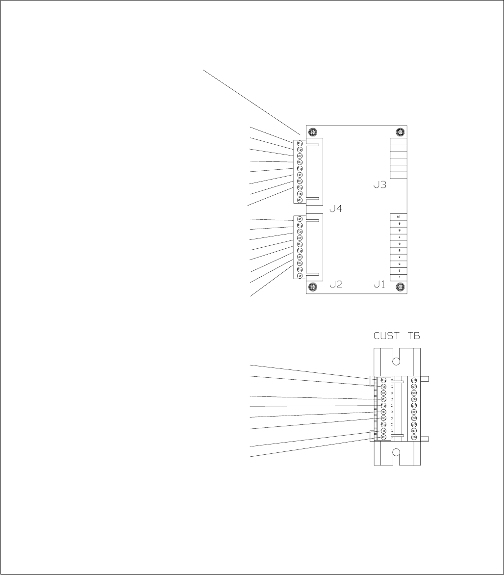
NOTE All building alarm inputs or remote features require an isolated normally-open contact or switch (rated at
24 Vdc, 20 mA minimum) connected between the alarm input and common terminal as shown. All control wiring and
relay and switch contacts are customer-provided.
NOTE Regardless of how you assign the building alarms, the default is to display the alarms as Building Alarm 1,
Building Alarm 2, and so on, on the monitor panel. Use twisted-pair wires for each alarm input and common.
1
10
CUSTJ4
CUSTJ2
1
10
10
1
RELAY #1 NC
RELAY #1 COMMON
RELAY #1 NO
RELAY #2 NC
RELAY #2 COMMON
RELAY #2 NO
BUILDING ALARM #2
BUILDING ALARM #2-RETURN
BUILDING ALARM #3
BUILDING ALARM #3-RETURN
BUILDING ALARM #4
BUILDING ALARM #4-RETURN
BUILDING ALARM #5
BUILDING ALARM #5-RETURN
REPO
REPO COMMON
REMOTE TO UPS RETURN
REMOTE TO UPS
REMOTE TO BYPASS RETURN
REMOTE TO BYPASS
CB3-AUX #2*
CB3-AUX #2
INVERTER I/O BOARD
(USED ONLY IN MULTI-MODULE
APPLICATIONS USING AN SBM)
BUILDING ALARM #1
BUILDING ALARM #1 RETURN
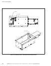
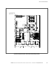
Figure A‐21. Output/Inverter Cabinet – PCM 2 Customer Interface Wiring