


USING FEATURES AND OPTIONS
EATON Powerware
®
9315 UPS (500–750 kVA) Installation and Operation Manual S 164201244 Rev E www.powerware.com
10-4
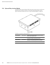
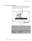
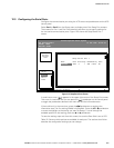
10.4 Optional Relay Interface Module
The optional Relay Interface Module (RIM) uses relay contact closures to indicate the
operating status and alarm condition of the Parallel Capacity/Redundant system.
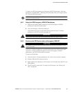
Figure 10‐2 shows the RIM with its four 15‐pin connectors labeled J1 through J4.
Figure 10‐2. RIM
The RIM can provide the following signals:
UPS AVAILABLE Pins 1 and 12 Contacts are closed when the UPS is operating in Normal
mode or ready to supply the load.
UPS OFF LINE Pins 3 and 13 Contacts are open when the UPS is offline. Contacts are
closed when the UPS is poerating Normal mode.
BATTERY WEAK Pins 5 and 14 Contacts are closed when approximately two minutes of
battery time is remaining, before the critical load is lost.
UTILITY FAILURE Pins 6 and 15 Contacts are closed when Utility Failure is detected.