


EATON Powerware
®
9315 UPS (500–750 kVA) Installation and Operation Manual S 164201244 Rev E www.powerware.com
9-1
Chapter 9 UPS Operating Instructions
This chapter describes the UPS controls and instructions for operating the UPS
system.
NOTE Before starting the UPS, ensure all installation tasks are complete and an authorized Eaton Customer
Service Engineer has performed a preliminary startup. The preliminary startup verifies all electrical
interconnections to ensure the installation was successful and the system operates properly.
NOTE The following procedures are applicable for systems with the optional internally installed rectifier
input breaker CB1 and inverter output breaker CB3.
NOTE For System Bypass Module (SBM) operation in a multi‐module system, refer to the Powerware 9315
Parallel Capacity/Redundant UPS Installation and Operation Manual.
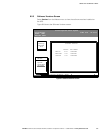
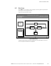
9.1 UPS Controls and Indicators
The controls and indicators identified and described in this section are used to control
and monitor UPS operation. Figure 9‐1 shows the UPS controls and indicators.
Input/Rectifier Cabinet Output/Inverter Cabinet Module Bypass
Cabinet (MBC)
Control Panel
Input Breaker
CB1 (optional)
Output Breaker
CB3 (optional)
Backfeed Protection
Breaker FBP
Bypass
Breaker CB4
Figure 9‐1. UPS Controls and Indicators
Figure