


COMMUNICATION
EATON Powerware
®
9315 UPS (500–750 kVA) Installation and Operation Manual S 164201244 Rev E www.powerware.com
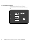
12-2
13
12
10
11
9
NOT USED
NOT USED
NOT USED
NOT USED
NOT USED
NOT USED
RS‐232 DTR
NOT USED
–12V
NOT USED
NOT USED
NOT USED
23
21
19
17
15
1
5
4
3
2
GND
RS‐232 TXD
RS‐232 RXD
RS‐232 RTS
RS‐232 CTS
6
8
7
RS‐232 DSR
RTN
+12V
NOT USED
NOT USED
NOT USED
NOT USED
NOT USED
24
22
25
20
18
16
14
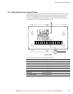
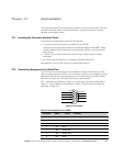
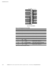
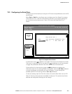
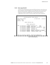
Figure 12‐2. Port 2 (DB‐25)
Table 12‐2. Pin Assignments for Port 2 (DB‐25)
Pin Number Symbol Function Comments
1 GND Chassis Ground
2 TXD Transmit Data Input to UPS
3 RXD Receive Data Output from UPS
4 RTS Request to Send Input to UPS
5 CTS Clear to Send Output from UPS
6 DSR Data Set Ready Output from UPS
7 RTN Return
8 +12V +12 Volts Output from UPS ‐ always true
20 DTR Data Terminal Ready Input to UPS ‐ typically not used by UPS
22 –12V –12 Volts Output from UPS ‐ always true
NOTE Pins 5 and 6 are tied together internally.