


COMMUNICATION
EATON Powerware
®
9315 UPS (500–750 kVA) Installation and Operation Manual S 164201244 Rev E www.powerware.com
12-3
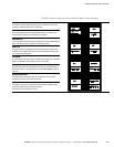
12.3 Configuring the Serial Ports
Configure the communication port using the LCD screen and pushbuttons on the UPS
control panel.
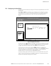
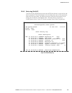
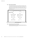
Select Port 1 or Port 2 from the Setup menu to display one of the Setup Port screens.
The screens for Port 1 and Port 2 are identical, and allow you to specify settings for
the two serial communication ports. Figure 12‐3 shows the Setup Serial Port 1
screen.
Statistics Graphics Setup
Setup
Port 1
Uninterruptible Power System
UPS System Normal
EventsMeters
Setup Serial Port 1
Rate
9600
Data/Stop
8 1
Handshaking
XON / XOFF
Save
NO
Time
Mode
TERMINAL
Port 2
Battery
100%
Percent
ALARM: NONE
NOTICES: NONE
15 JUL 1998 09:25:42
Figure 12‐3. Setup Serial Port 1 Screen
A small return arrow ( ) appears in the upper right corner of the Setup Port screen.
This arrow is a reminder that you can press the
pushbutton on the control panel
to toggle the pushbuttons between the menu box and the information area.
If the scroll bar is in the menu box, press the
pushbutton to toggle to the
information area. The first setting (Mode) is highlighted. Press the
or pushbutton
to move the highlight to the setting you want to change. To scroll through the
available options for that setting, press the
or pushbutton.
To save the settings upon exit from this screen, be sure the Save field is set to YES.
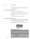
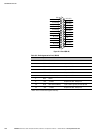
Table 12‐3 shows which options are available for each port. The sections that follow
describe the configuration settings you can change.