


USING THE CONTROL PANEL
EATON Powerware
®
9315 UPS (500–750 kVA) Installation and Operation Manual S 164201244 Rev E www.powerware.com
8-5
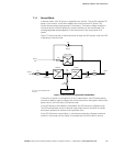
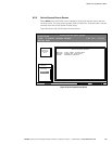
8.5.1 System Meters Screen
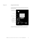
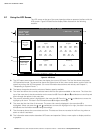
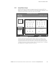
Figure 8‐4 shows the LCD screen as it appears when you first start the UPS. The
Meters menu is displayed in the menu box, with the System option highlighted. In the
information area, the system meters show their current readings.
Uninterruptible Power System
System Normal
Meters
System
Load Amps
Events Statistics Graphics Setup
Input Output
Bypass Battery
VAB
nnn
VBC VCA
KW
nnn
KVA
nnn
IA IB IC
FREQ
nn.n
PF
0.nn
V
nnn
I
nn
Meters
nnn
nnn nnn
nnnnnn
VAB
nnn
VBC VCA
nnn nnn
IA IB IC
nnn nnnnnn
IN
nnn
VAB
nnn
VBC VCA
nnn nnn
FREQ
nn.n
KVA
nnn
KW
nnn
PF
0.nn
Battery
48.5
Minutes
Versions
+
ALARM: NONE
NOTICES: NONE
4 MAY 1999 09:25:42
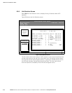
Figure 8‐4. System Meters Screen
The Input area shows the phase‐to‐phase voltage, frequency, and phase current
of the incoming utility, followed by the kVA, kW, and power factor measurements.
The output area shows the same information for the power being output by the UPS.
The Bypass area shows the phase‐to‐phase voltage of the bypass source. The Battery
area displays the DC voltage (V) and the DC current (I).