


INSTALLING OPTIONAL ACCESSORIES
EATON Powerware
®
9315 UPS (500–750 kVA) Installation and Operation Manual S 164201244 Rev E www.powerware.com
6-6
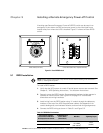
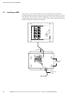
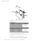
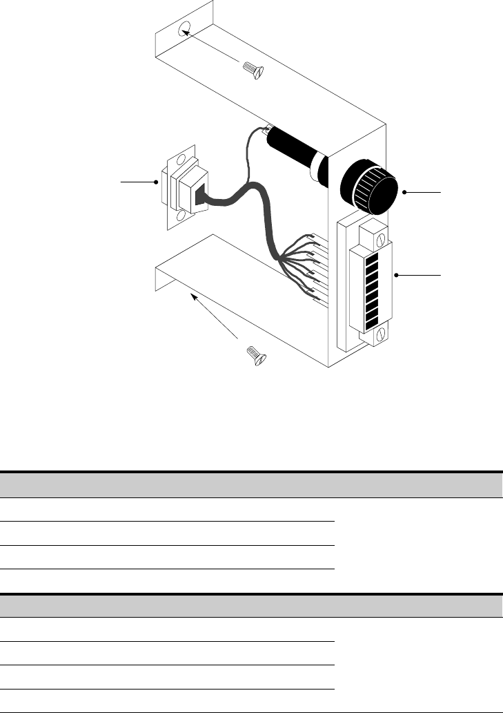
Connect to
Port 1 (DB‐9) on
Customer Interface Panel
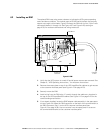
Fuse
Terminal
Block
(TB3)
Figure 6‐4. Terminal Block Bracket
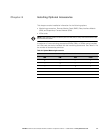
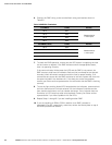
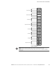
6. Connect RIM wiring to the terminal block using the terminations shown in
Table 6‐3.
Table 6‐3. RIM Wire Terminations
From RIM A To UPS Remarks
TB1‐4 TB3‐1
Twisted wires (4)
1–2 turns per 3”
TB1‐5 TB3‐2
TB1‐6 TB3‐3
TB1‐7 TB3‐4
From RIM B (If Used) To UPS Remarks
TB1‐4 TB3‐5
Twisted wires (4)
1–2 turns per 3”
TB1‐5 TB3‐6
TB1‐6 TB3‐7
TB1‐7 TB3‐8
7. Contact your Eaton service representative for verification and testing of the RIM
and its connections prior to making connections to J1 through J4.
You can order interface cables separately for connecting to the 15‐pin D‐sub
connectors.
8. Repeat Steps 1 through 7 if you are installing another RIM.
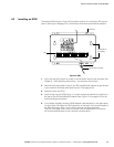
9. If you are installing an SCM in addition to an RIM, proceed to paragraph 6.3;
otherwise, secure the access plate on top of the UPS Input/Rectifier cabinet.