


EATON Powerware
®
9315 UPS (500–750 kVA) Installation and Operation Manual S 164201244 Rev E www.powerware.com
7-1
Chapter 7 Understanding UPS Operation
The Powerware 9315 is a continuous duty, solid‐state UPS that supports the
following equipment: process control, data processing, telecommunications/PBX,
research, and medical. The Powerware 9315 maintains power to the critical loads
during commercial electrical power brownout, blackout, overvoltage, undervoltage,
and out‐of‐tolerance frequency conditions.
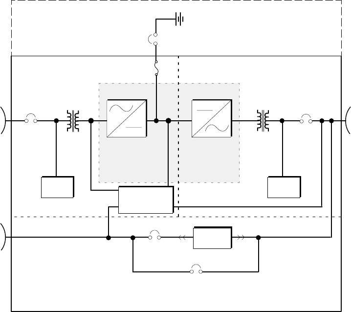
In this manual, the power required by your equipment is called the critical load. The UPS
supplies the critical load with conditioned power that is synchronized with your utility
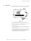
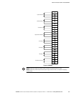
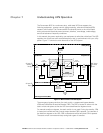
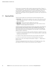
power. Figure 7‐1 shows the main elements of the UPS system.
AC Output
to Critical
Load
AC Input to
Rectifier/
Charger
Bypass
Breaker
CB4
Input
Filter
Output
Breaker
CB3
Backfeed
Protection
Breaker FBP
Battery String
Output/InverterInput/Rectifier
Battery
Breaker
CB2
F30
F31
Input
Transformer
Input
Breaker
CB1
AC Input to
Bypass
Module Bypass Cabinet (MBC)
Input
Filter
Digital
Metering
Rectifier/
Charger
Inverter
Power
Processing Unit
Output
Transformer
Static
Switch
Figure 7‐1. Main Elements of the UPS System
The emergency bypass consists of a static switch, a wraparound bypass breaker
(CB4) and a Backfeed Protection Breaker (FBP). The FBP is located in series with the
static switch and opens so that the UPS cannot backfeed the bypass source.
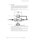
For manual transfers to bypass, the static switch is not used. During the transfer, CB4
is closed and verified and then inverter output breaker CB3 is opened. For transfers of
the load from bypass to the UPS, CB3 is closed and verified and then CB4 is opened.
The static switch is armed and ready during both types of transfers.
Figure