


INSTALLATION REFERENCE
EATON Powerware
®
9315 UPS (500–750 kVA) Installation and Operation Manual S 164201244 Rev E www.powerware.com
A-14
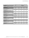
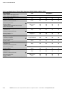
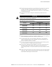
Table F. Input/Output Ratings and External Wiring Requirements (PW9315-700/500 and PW9315-750/562)
Basic Unit Rating
PW9315-750/500 at 0.8 Lagging pF Load
PW9315-750/562 at 0.9 Lagging pF Load
Units Rating 50/60 Hz
kVA/kW 625/500 625/500 625/562 625/562
Input and Output Voltage Volts 480 600 480 600
AC Input to UPS Rectifier (0.95 Min. pF)
(3) Phases, (1) Neutral, (1) Ground
A
Amps* 951 761 984 787
Minimum Conductor Size
Number per Phase
* Maximum amps includes full load current plus
battery recharge current
AWG or kcmil
(each)
400
(4)
350
(4)
500
(4)
350
(4)
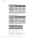
AC Input to MBC (UPS Bypass)
Full Load Current
(3) Phases, (1) Neutral, (1) Ground
B
Amps 752 601 752 601
Minimum Conductor Size
Number per Phase
AWG or kcmil
(each)
500
(3)
350
(3)
500
(3)
350
(3)
DC Input from Battery to UPS
(1) Positive, (1) Negative
C
Vdc
Amps @ (2.0V/cell)
384
1370
384
1370
384
1542
384
1542
Minimum Conductor Size
Number per Pole
AWG or kcmil
(each)
500
(6)
500
(6)
600
(6)
600
(6)
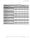
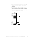
AC Output to Optional SBM
Full Load Current
(3) Phases, (1) Neutral, (1) Ground
E
Amps 752 601 752 601
Minimum Conductor Size
Number per Phase
AWG or kcmil
(each)
500
(3)
350
(3)
500
(3)
350
(3)
AC Output to Critical Load
Full Load Current
(3) Phases, (1) Neutral, (1) Ground
D
Amps 752 601 752 601
Minimum Conductor Size
Number per Phase
AWG or kcmil
(each)
500
(3)
350
(3)
500
(3)
350
(3)
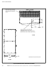
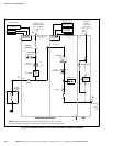
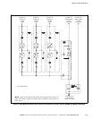
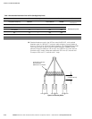
NOTE Callout letters A, B, C, D, and E map to Figure A‐8.