


EATON Powerware
®
9315 UPS (500–750 kVA) Installation and Operation Manual S 164201244 Rev E www.powerware.com
12-1
Chapter 12 Communication
This chapter describes the communication features of the Powerware 9315 UPS and
provides information about connecting hardware, configuring the ports, changing
settings, and changing modes.
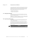
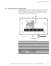
12.1 Locating the Customer Interface Panel
The customer interface panel inside the UPS contains:
S Two serial communication ports, one DB‐9 and one DB‐25.
The ports provide a computer interface to a Remote Monitor Panel (RMP), Relay
Interface Module (RIM), Supervisory Contact Module (SCM), or remote terminal
and/or printer.
S A 120 Vac, 0.2A convenience outlet for powering a modem used for remote
notification.
S An X-Slot communication bay for installing an optional X-Slot card.
See Appendix A for the UPS customer interface panel location.
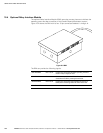
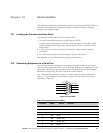
12.2 Connecting Equipment to a Serial Port
The UPS serial communication ports are designed to accept a wide variety of data
communication equipment (DCE), such as terminals, printers, and computers. Use an
appropriate cable for the type of equipment you are connecting to the UPS. Cables
should be no longer than 16m (50 ft) and have a male connector.
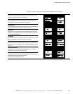
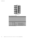
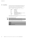
Port 1 cable pins are identified in Figure 12‐1 and the pin functions are described in
Table 12‐1. Port 2 cable pins are identified in Figure 12‐2 and the pin functions are
described in Table 12‐2.
NOT USED
485–
485+
RETURN
7
8
9
1
5
4
3
2
+24V
RS‐232 TXD
RS‐232 RXD
NOT USED
RETURN
6
Figure 12‐1. Port 1 (DB‐9)
Table 12‐1. Pin Assignments for Port 1 (DB‐9)
Pin Number Symbol Function Comments
1 +24V +24 Volts DC
2 TXD Transmit Data Input to UPS
3 RXD Receive Data Output from UPS
5 RTN Return
7 485+ RS‐485 + Data
8 485– RS‐485 – Data
9 RTN Return
Figure